Results
Configuring a variable
The following variables may be configured individually:
-
Categories (These variables are subject to the appropriate costs.)
-
Time-based / cyclic trigger
-
Trigger based on variable values
-
Alarm-based trigger
-
Requirement
 |
Software option In order to use the variable data, you need the "Path length evaluation" software option (6FC5800-0AM53-0YB0). |
Procedure
-
In the launchpad, click "Asset Manager" and select the required asset in the left-hand side of the window.
-
Click the "MTA Asset Config" icon.
-
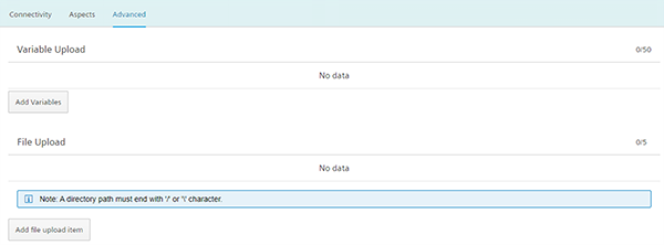
Open the "Advanced" tab.
-
Adding variables
-
Click on "Add variable".
A new input field is displayed. -
Enter a title for the variable in the input field.
-
-
Add file upload element
-
Click on "Add file upload element"
-
In the input field, enter a name for the file upload element.
-
-
Click on the arrow to the left of the input field to perform additional settings.
Recording type and data acquisition of the cyclic trigger and alarm trigger are available.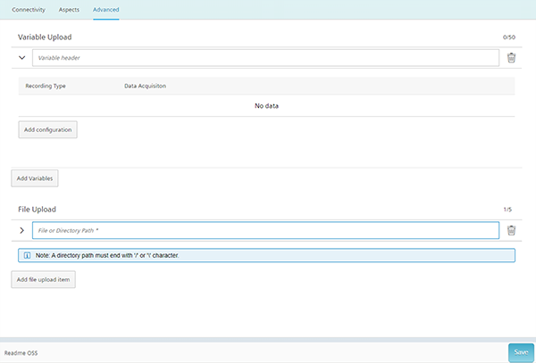
-
Click on the "Edit" icon to create individual cycles or for systematic selection of alarms.
-
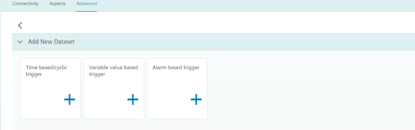
Click on the "Add configuration" button to add a new data set.
The following selection is available:-
Time-based / cyclic trigger
-
Trigger based on variable values
-
Alarm-based trigger
-
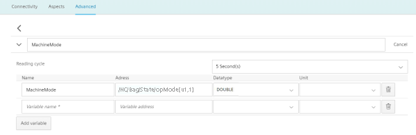
Time-based / cyclic trigger
|
Parameters |
Description |
|
|---|---|---|
|
Aspect name |
Enter a name to designate a common group of variables. The name must be unique and not exceed 255 characters. |
|
|
Name |
In the variable set, enter a name of the variable to be sensed. Example: Jerk_MA_MX The variable name must have at least three characters. The first character must not be a number or an underscore. Do not use square brackets in the notation of a variable! Do not use any umlauts (special German characters), e.g. "ä", "ö", "ü"! |
|
|
Address |
Enter the address or the path of a variable. Examples: |
|
|
Axis data: |
/Nck/MachineAxis/AATRAVELCOUNT[1] /Nck/MachineAxis/AATRAVELDIST[2] |
|
|
Channel data: |
/Channel/ChannelDiagnose/CuttingTime[u1] /Channel/ChannelDiagnose/OperatingTime[u1] |
|
|
Machine operating mode: |
/Bag/State/opMode[u1] |
|
|
Data type |
From the drop-down list select the data type of the variable:
Note: If values exceed the floating-point number accuracy, they are displayed with faulty decimal places. |
|
|
Unit |
From the drop-down list, select the physical unit of the variable. Example: m/s3 |
|
|
A reading cycle |
The sampling rate of the data acquisition is specified with this value. From the drop-down list select the time period. Example: 5 seconds |
|
Procedure
-
Click on the "Time-based / cyclic trigger" function.

-
Enter a name in the "Aspect name" input field and click the ">" arrow to the left of the input field.
Further input fields and drop-down lists open.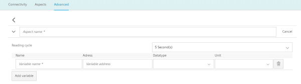
-
Enter the variables in the input fields as in the following example.
-
Click the "Add variable" button to add a new variable.
If necessary, repeat this step. -
Click the "Delete" icon to delete individual variables.
-
Click on the "Cancel" button to reset the entries.
-
-
Click the "Save" button to accept the entries.
Changing saved variable setsNOTE
After saving, you can only change the following properties of the variable set:
-
Address of a variable
-
Query cycle of the variable set
If you want to change further properties, you must delete the variable set and create a new one. The previously acquired data is lost!
-
-
Click the "Exit" button to close the property window without saving the entries.
You return to the overview of the assets.
Trigger based on variable values
Any variables for which a communication mechanism exists can be linked logically with the variable trigger.
For this you have the following options:
|
Parameters |
Description |
|
|---|---|---|
|
When the variable |
||
|
Data acquisition name |
Enter a previously created variable. |
|
|
Variable address |
Shows the address of the variable. |
|
|
Data type |
From the drop-down list select the data type of the variable.
|
|
|
From the drop-down list, select the comparison operation that is restricted to the format of the variables:
|
||
|
Variable value |
Enter a value. |
|
|
With the following configuration |
||
|
Debounce time |
Enter the debounce time |
|
|
min |
Select the duration of the debounce time from the drop-down list. Minimum: 30 s Maximum: 24 h |
|
|
Hysteresis |
Activate the checkbox if you want to include hysteresis. |
|
|
Activate the "Relative" option button if the relative value in relation to the comparison value is to be recorded. Activate the "Absolute" checkbox if the absolute values in relation to the comparison value is to be recorded. Retriggering to the comparison value only occurs if the actual value differed from the comparison value by more than the stated hysteresis. Enter a comparison value. This is restricted depending on the selection of the address format. |
||
|
Then |
||
|
Record the subsequent value |
Select the value from the drop-down list. |
|
|
Variable address |
Shows the address of the variable. |
|
|
Data type |
From the drop-down list select the data type of the variable:
|
|
|
With the following configuration |
||
|
Recording for |
Duration Enter the duration Minimum: 30 s Maximum: 24 h |
Time unit Select the time unit from the drop-down list. |
|
Within the cycle time |
Cycle Enter a cycle Minimum: 30 s Maximum: 24 h |
Time unit Select the time unit from the drop-down list. |
Procedure
-
Click on the "Trigger based on variable values" function to define dependencies.

-
Select a variable and open further input fields and drop-down lists with the arrow.
-
Enter the dependencies.
Click the "Save" button to save the variable trigger.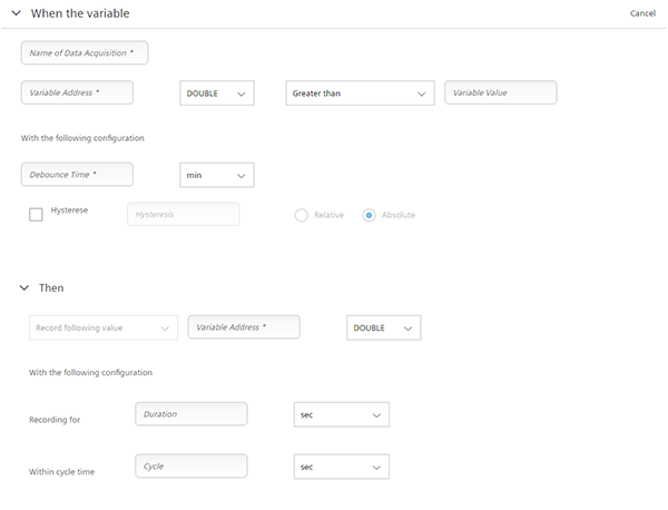
Alarm-based trigger
The alarm-based trigger reacts to all alarms programmed in the control.
These alarms also contain the user range of alarm numbers that are assigned the machine functions for the machine diagnostics. If machine diagnostics are not performed on the basis of alarm numbers, these error messages cannot be integrated. The alarm numbers that are triggered can be entered individually, in groups, or in series. It is also possible to remove individual alarms or groups from a selection. You can link conditions that themselves do not activate a trigger.
|
Parameters |
Description |
|---|---|
|
Alarm name |
Enter a descriptive name for the alarm. |
|
Alarm acknowledgement filter |
|
|
INCLUDED |
|
|
Alarm codes: |
Enter the alarm numbers or the alarm IDs that activate the trigger. The alarms are entered in the following notation:
The alarm list must not exceed 200 characters. |
|
Alarm intervals: |
Enter the alarm limits:
All alarms between 0 and 99999 are included. |
|
EXCLUDED |
|
|
Alarm codes: |
Enter the alarm numbers that do not activate the trigger. The alarms are entered in the following notation:
The list of alarm numbers must not exceed 200 characters. |
|
Alarm intervals: |
Enter the alarm limits:
All alarms between 0 and 99999 are included. |
|
New alarm filter |
|
|
INCLUDED |
All fields, the same as under "Alarm Acknowledge Filter" - "INCLUDED" |
|
EXCLUDED |
All fields, the same as under "Alarm Acknowledge Filter" - "EXCLUDED" |
Procedure
-
Click the "Alarm based trigger" function to define alarm properties, e.g. when an alarm should be displayed.

-
Enter a name for the alarm and specify the properties.
Click the "Save" button to save the alarm based trigger.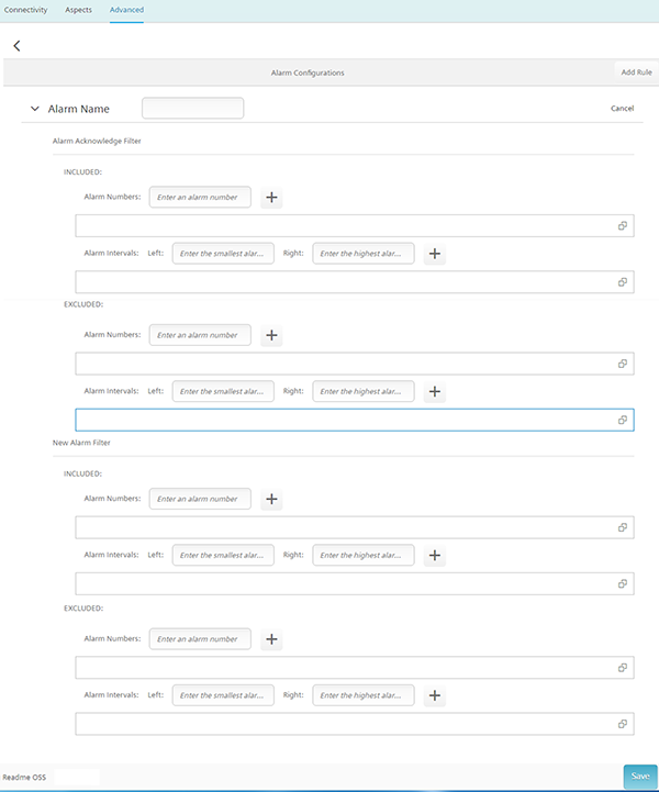
Further information
Further information about the NC variable can be found in the
List Manual SINUMERIK 840D sl NC variables
NOTE
A read cycle time selection of 5 seconds allows the creation of a maximum of 5 variables.
Otherwise, up to 50 variables can be created.