Results
Defining parameters
For correct measurement results, the axis parameters must be set both in the SINUMERIK Edge application and on the SINUMERIK control.
Parameters
The following parameters are displayed in the SINUMERIK Edge application of Analyze MyMachine /Condition:
|
Parameters |
Description |
|---|---|
|
Channel name: axis |
Displays channel name and axis identifier. Additionally it specifies whether it is a linear axis or axis of rotation. |
|
JMot ([kg]/[kgm2]) |
Input field for drive parameters. For linear direct drives the value is specified in kg, otherwise in kgm2. |
|
Mechanical system |
Selecting the mechanical axis type for linear axes. The following axis types are supported:
This field is not displayed for rotary axes. |
|
Micrometer step |
Input field for the step width in micrometers for linear axes with rack-and-pinion drive. The default setting is 10 μm. The value can be changed in the range 1 μm to 100 μm. For linear axes with ball screw drive the default setting is 1 μm. This value cannot be changed. If the SINUMERIK control operates with values in inches, the corresponding inch values are displayed. This field is not displayed for rotary axes. |
|
Gravity compensation |
Check box for activating gravity compensation. For axes whose holding force/torque varies as a function of their position due to gravity (e.g. swivel axes). Vertical axes that have a constant holding force/torque do not require compensation. The compensation is deactivated by default. |
|
Path of the AST strategy file |
Input box for specifying the path to the strategy file. The strategy file is generated by the AST function in SINUMERIK Operate. |
Requirement
Analyze MyMachine /Condition was started at the PC.
You are logged in with the "OEMMachineCommissioningEngineer" user role.
Procedure
-
Open the menu on the left in the title bar of Analyze MyMachine /Condition.
-
Select the entry "Axis settings".
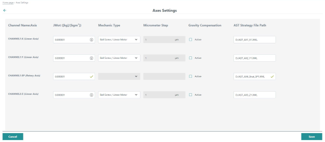
The application moves to the "Axis settings" page:https://<ip-address-of-edgebox>:5443/analyzemymachineui/axissettings
-
For the displayed axes, enter the corresponding "JMot" drive parameters.
The axes are preassigned with the value 0.000001 [kgm2, kg] and must be adapted.
-
For all linear axes, select the mechanical type of axis.
-
Enter the "micrometer step" for linear axes of the type "rack-and-pinion drive".
-
For axes that are affected by gravity over the distance, select the "Gravity compensation" check box.
-
If the axis is tested for frequency response, enter the path to the AST strategy file.
-
Make sure that the necessary information is entered on the "Axis Settings" page for all axes in all channels, otherwise you will obtain incorrect measurement results.
Drive parameters on the SINUMERIK control
-
In SINUMERIK Operate, press key <MENU SELECT> or <F10>.
-
Select the "Setup" operating area.
-
Press softkey "Mach. data".
-
Press softkey "Drive parameter".
The list of parameters is displayed. -
Search for parameter "p341" for your axis.
-
For each axis, set the corresponding parameter values in the "JMot" column.
Use the "+" and "-" softkeys to navigate to the next or previous axis.