Results
Configure measurement
Notes on the distance
-
The measuring program of an axis or measurement group should not exceed 45 min, as otherwise it is possible that invalid measurement results will be obtained.
-
For frequency response tests, the traversing paths are used that have been defined in the AST configuration in SINUMERIK Operate. This means that the limit values specified on the "Basic Configuration" tab are not evaluated if you only select frequency response as the characteristic value.
-
If you change the unit of measurement used on the SINUMERIK control, Analyze MyMachine /Condition is not adjusted immediately. It is very probable that the application will calculate values incorrectly. Restart Analyze MyMachine /Condition whenever the measurement unit on the SINUMERIK control is changed over.
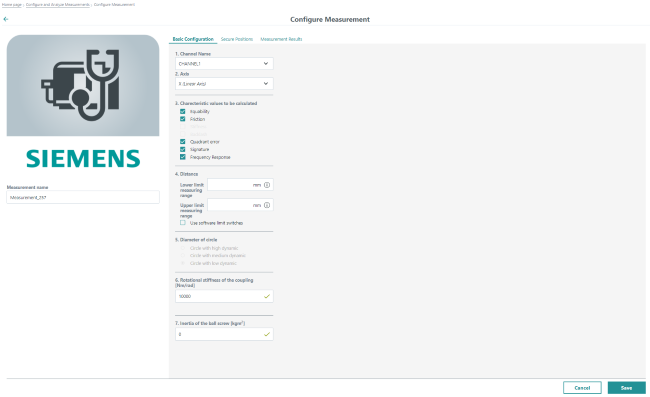
Elements in the "Basic Configuration" tab
|
Function |
Description |
|
|---|---|---|
|
Name of the measurement |
Input field for the unique name of the measurement |
|
|
Channel name |
Selection of the channel to be tested |
|
|
Axis |
Selection of the axis to be tested |
|
|
Characteristic values to be calculated |
Selection of the characteristic values that must be calculated for the measurements:
|
|
|
Distance |
||
|
Lower limit measuring range |
The starting point for measurement travel is defined here. |
|
|
Upper limit measuring range |
The end point of measurement travel is defined here. |
|
|
Use software limit switch |
Checkbox to activate the software limit switch of the particular axis |
|
|
Diameter of circle |
||
|
Circle with high dynamic response |
For measurements with a high dynamic response (r = 10 mm, F = 5000 mm/min) |
|
|
Circle with medium dynamic response |
For measurements with a medium dynamic response (r = 15 mm, F = 3000 mm/min) |
|
|
Circle with low dynamic response |
For measurements with a low dynamic response (r = 20 mm, F = 1000 mm/min) If the axis is configured as a rack & pinion axis, this option is preset as the default setting and cannot be changed. |
|
|
Rotational stiffness of the coupling [Nm/rad] |
Field to enter the rotational stiffness of the coupling |
|
|
Inertia of the ball screw [kgm2] |
Field to enter the moment of inertia of the ball screw |
|
|
Release measurement |
The button sets the measurement to "Released" status. This button becomes visible when a measurement has been saved and all the required values have been defined. |
|
|
Back |
The small arrow at the top left of the title bar aborts the current processing and returns to the previous page. |
|
|
Edit |
This button opens an existing measurement for editing. This button becomes visible when a measurement has been saved. |
|
|
Save |
The button saves the changes. This button becomes visible when a measurement has been edited. |
|
|
Cancel |
This button is displayed when you create a new measurement. The button is not visible when you edit a measurement. |
|
Procedure
-
Enter a unique name for the measurement in the "Measurement name" field.
-
Select the required channel from the "Channel name" drop-down list.
Each channel has its own, unique list of axes. -
Select the required axis from the "Axis" drop-down list.
Each axis has a specified software limit that is checked.
-
Activate the appropriate checkbox to select the required characteristic values.
-
Enter the required limit values in the fields "Lower limit measuring range" and "Upper limit measuring range".
- OR -
Activate the checkbox "Set software limit switch" to accept the software limit switch related to an axis.
The recommended setting is from lower to upper measurement range limit.If you enter a distance that is too small for calculation of the selected characteristic value, you will receive a warning.
-
If you have selected the "Quadrant error" characteristic value, specify the diameter of circle by activating the appropriate option button.
-
Enter the rotational stiffness of the coupling in Nm/rad in the corresponding input field.
-
Enter the moment of inertia of the ball screw in kgm2 in the corresponding input field.
-
Click the "Save" button.
The selection is saved. The new measurement is displayed in the list on the "Configure and Analyze Measurements" page.After being set up, the measurement has the status "Created" if not all of the necessary data has yet been entered.
The measurement has the status "Defined" if all of the necessary data has been entered.- OR -
Click the "Cancel" button to cancel the input.
- OR -
Click the small arrow on the left of the title bar to abort the current input and return to the previous page.
NOTE
If you want to configure a measurement for a spindle, ensure that the selected spindle is configured as an axis.
In addition, Analyze MyMachine /Condition supports the following axis types:
Master / slave: Only the master axis is measured.
Gantry: Only for the linear axes, whereby only the leading axis is measured.
The axes of a newly configured channel in the SINUMERIK control are only offered for selection after Analyze MyMachine /Condition has been restarted.
If two different channels of an axis have the same axis ID, then Analyze Mymachine /Condition displays the first axis on the configuration page.