ET200 Sensor Adapter
Introduction
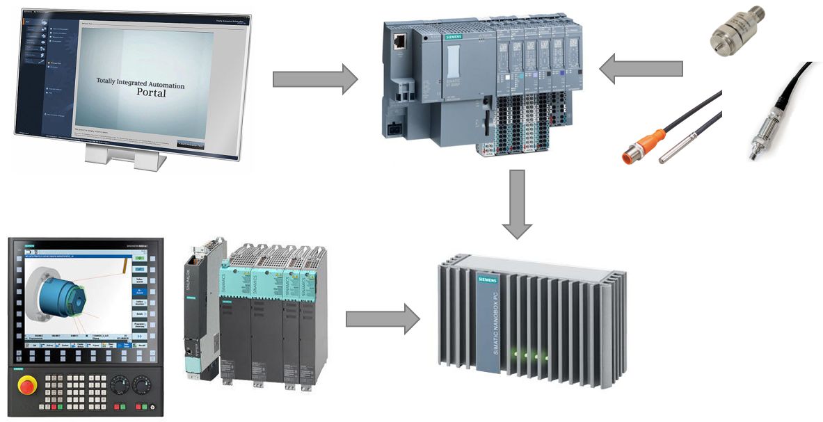
The ET200 Sensor Adapter application allows the user to collect low / high frequency sensor data from the matching configuration of the of the Siemens SIMATIC ET 200SP analog and / or digital interfaces. The gathered sensor information is provided through databus in a merged comma-separated values (csv) file for further analysis in any appropriate application. In this documentation for example we assume that you are using Analyze My Workpiece /Capture4Analysis for receiving output data.
This documentation presents only the installation and use of a possible solution from the countless variations. In our example, the system supports 4 analog channels with 10 kHz sampling rate separately, and 8 digital channels at 2 kHz each, plus a PT100 resistance thermometer at maximum 2 kHz sampling rate. All the hardware requirements and configurations are reflecting to this exemplified setup. ET200 Sensor Adapter was thoroughly tested and measured with the corresponding configuration.
Experimental: Optionally the collected data can be combined with the Sinumerik Adapter HF data in one, time-synchronized JSON output. For that, you additionally need to use "ET200_sensor_timesync" and "ntp_server" applications. Current version of the timesync app was not tested on many ET200 configurations. This documentation will help you test the feature, but if not interested, you can skip NCU- and timesync-specific paragraphs.
Hardware requirements
SIMATIC ET 200SP:
| Component | Name | Article number | Single parts | Unit | Quantity |
|---|---|---|---|---|---|
| ET 200SP | DIN rail 35 mm, length: 483 mm, for 19" cabinets | 6ES5710-8MA11 | 1 | Pieces | 1 |
| ET 200SP Power (optional) | SIMATIC ET 200SP PS, 1-phase, 24 V DC / 5 A | 6EP7133-6AB00-0BN0 | 1 | Pieces | 1 |
| ET 200SP CPU | CPU 1512SP-1 PN | 6ES7512-1DK01-0AB0 | 1 | Pieces | 1 |
| ET 200SP CPU | Memory card, 12 MB | 6ES7954-8LE03-0AA0 | 1 | Pieces | 1 |
| ET 200SP CPU | BusAdapter 2xRJ45 | 6ES7193-6AR00-0AA0 | 1 | Pieces | 1 |
| ET 200SP I/O Interface Module | IM 155-6 PN HF/2 V4.2 | 6ES7155-6AU01-0CN0 | 1 | Pieces | 1 |
| ET 200SP I/O Interface Module | AI 2xU/I 2/4-wire HS | 6ES7134-6HB00-0DA1 | 1 | Pieces | 2 |
| ET 200SP analog input module | ET 200SP AI 4XRTD/TC 2-/3-/4-WIRE HF | 6ES7134-6JD00-0CA1 | 1 | Pieces | 1 |
| ET 200SP digital input module | DI 8x 24 V DC High Speed | 6ES7131-6BF00-0DA0 | 1 | Pieces | 1 |
| ET 200SP I/O Interface Module | BusAdapter 2xRJ45 | 6ES7193-6AR00-0AA0 | 1 | Pieces | 1 |
| ET 200SP I/O Interface Module | BU type A0, push-in terminals, without aux. terminals, new load group | 6ES7193-6BP00-0DA0 | 1 | Pieces | 2 |
| ET 200SP I/O Interface Module | BU type A0, Push-in terminals, without AUX terminals, bridged to the left | 6ES7193-6BP00-0BA0 | 1 | Pieces | 2 |
| Non-configured articles | PROFINET strain relief (5 units) | 6ES7193-6RA00-1AN0 | 4 | Package | 1 |
| Individual / network article | IE TP cord RJ45/RJ45, 4x2, 0.5 m | 6XV1870-3QE50 | 1 | Pieces | 1 |
Hint: The above configuration supports 4 analog, 8 digital and a analog PT100 thermometer, but regarding the actual use case it can be freely customized.
Various analog and digital sensors
It is possible to attach numerous of various sensors to the ET 200SP. Vibration sensors, accelerometers, thermometers, noise dosimeters, light sensors etc.
Specifically supported PT100 resistance thermometer
The ET 200SP analog interface specifically supports different resistance thermometers (see documentation here). In the described use case, the ifm electronic TS2289 was used.
Prerequisites:
- Industrial Edge for Machine Tools IPC: nanobox SIMATIC IPC227E or microbox SIMATIC IPC427E
- A Windows PC with TIA portal installed
- A Sinumerik NCU connected and configured to the Sinumerik Adapter on Industrial Edge for Machine Tools IPC (Optional, if using the experimental timesync app)
SIMATIC ET 200SP hardware configuration and wiring diagram
Schematic illustration of components
Wiring the EdgeBox & the SINUMERIK 840D sl
Note: Network switch necessary when using NCU and ET200
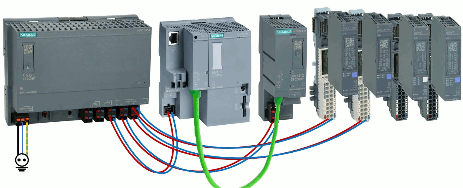
Wiring of the SIMATIC ET 200SP components
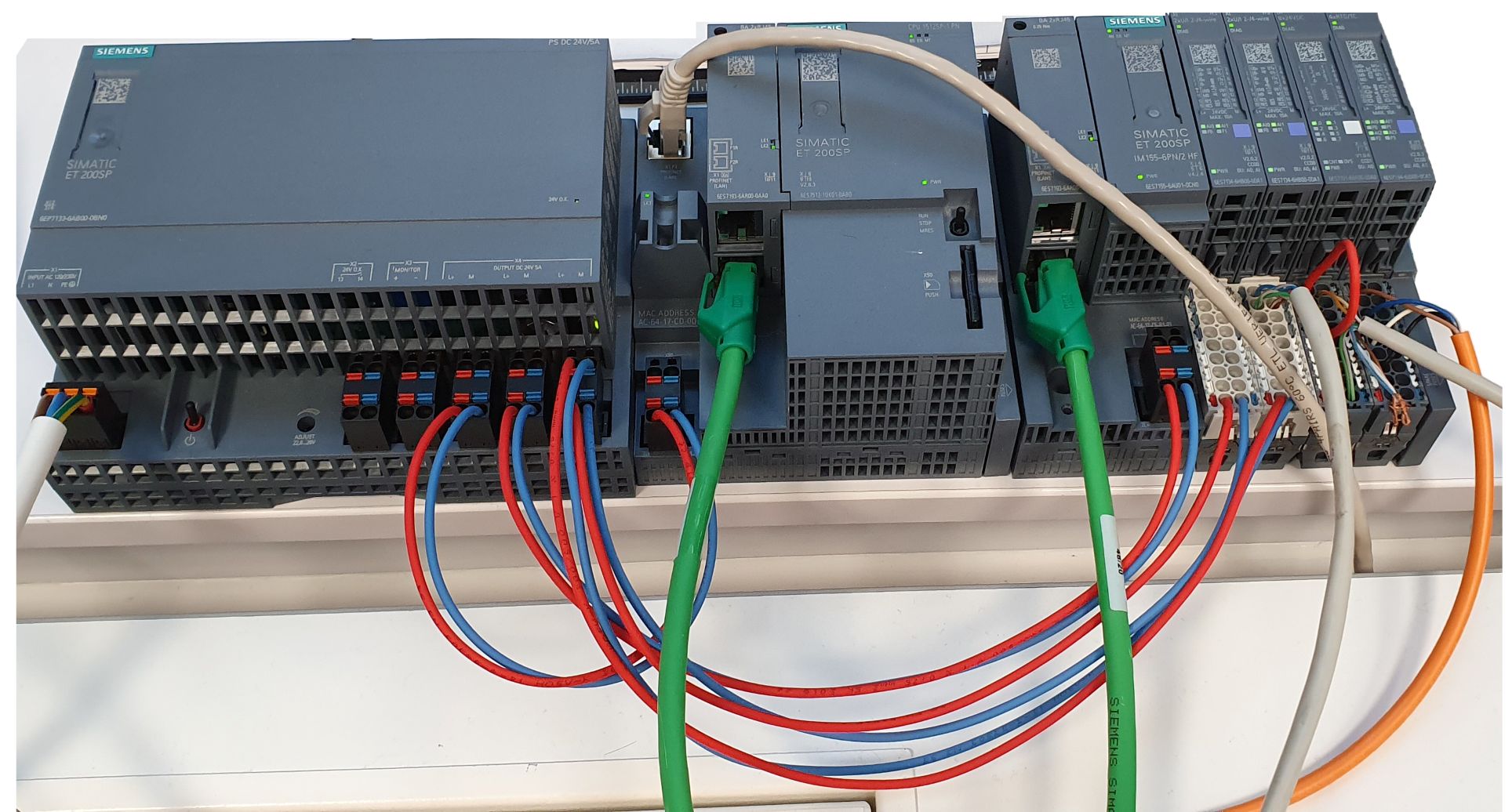
The following figure shows the ET 200SP components and their basic wiring without the sensor connections. The black/blue/yellow-green cables are connected to the main power source (EU AC230V/50Hz). The red/blue wires are the DC24V power cords to power the peripherals. The thick green cable is a RJ45/RJ45 Profinet cable. All components are mounted on a top-hat rail. It is important to use server modules as termination for the backplane bus.
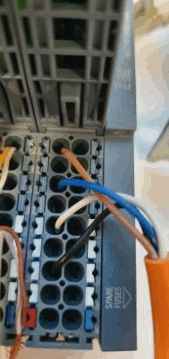
To connect a sensor to a digital or analog interface, please refer the appropriate interface modul's user manual. For an example, the 4-wire PT100 resistance thermometer is connected to the High Feature analog interface like this:
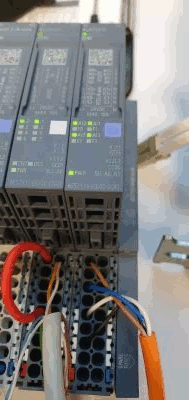
Note: During operation the overall assembled configuration looks like this.
Commissioning Industrial Edge for Machine Tools
Installation of the operating system on IPC
Connecting to the Insights Hub
Installation of the indapps
To use the ET200 Sensor Adapter, various Edge apps are required. These apps can be installed on the Edge via the Insights Hub Manage MySINUMERIK Edge App Management application. The Application Management guide provides help for installing and configuring Edge Apps. For the best result, please download the latest productive app version available in App Management.
Tip: To ensure a fast and smooth installation, all Edge Apps should be added one after the other (same for the installation of the app instances). Otherwise, the installation process may be disrupted.
App Overview
| AppName | Version | Description |
|---|---|---|
| adapterframework | 5.2.0-004 | AdapterFramework is a component for managing installed device adapters and App to App communication. |
| sinumerikadapter | 7.0.0-004 | SinumerikAdapter is a component for managing access to SINUMERIK 840Dsl or SINUMERIK ONE for getting low frequency and high frequency data from controller. |
| ntp_server | V2.0.2 | Provides an NTP server on the machinelan interface port 123, using the local time on the EdgeBox. |
| ET200_sensor_adapter | V1.0.0 | Adapter application for ET200 based sensor data acquisition solutions. Supporting multiple analog and digital input modules. |
| ET200_sensor_timesync | 0.8.0 | Provides Sinumerik HF Data extended with sensor data from ET200 Sensor Adapter synchronized on timestamps. The synchronization is done on the timestamps provided by the NCU and the ET 200SP. Please make sure that these devices have the same time. You can use ET200_ntp_server as an option to provide an NTP server accessible to both the NCU and the ET 200SP device. |
| amw4analysis | v2.3.0.0.12 | Analyze My Workpiece \/Capture4Analysis is a Industrial Edge for Machine Tools application which enables the user to acquire data from the SINUMERIK CNC controller, store it, and share it to both SIEMENS or any other application. |
Configuration of the Indapps
For error-free use of the apps, various parameters must be adjusted in the app settings. For configuration, the app can be started on the Edge. The configuration is done in a JSON editor of the App Management (Configuration of Indapps). Further information on the JSON file format is available at the following link.
ET200_sensor_timesync:
The "ET200_sensor_timesync" application can be configured through Insights Hub. The configuration stored in JSON format, a sample file with explanation is here.
ET200 Sensor Adapter:
Beside the possibility to configure on the Insights Hub, the ET200 Sensor Adapter application has a standalone graphical configurator user interface. Please read the ET200 Sensor Adapter Configurator documentation here.
Commissioning HF Probe and EdgeFs on the NCU
To be able to use the HF functionality on a SINUMERIK control, additional software must be installed on the SINUMERIK NCU.
TIA portal configuration
Procedure
1. Load preconfigured project into TIA Portal V16
Importing the TIA project on a Windows 10 based PC with preinstalled TIA Portal is so simple that you just have to double-click on the project file. The project contains the expected ET 200SP configuration, yet, smaller differences are possible, for example, in the physical order or number of the installed interfaces. You have to modify the project according to the real ET 200SP configuration.
Hint: The application download folder contains a V16 project file, which can be imported and used under TIA Portal version V17 and V18 too.
2. Check Hardware configuration:
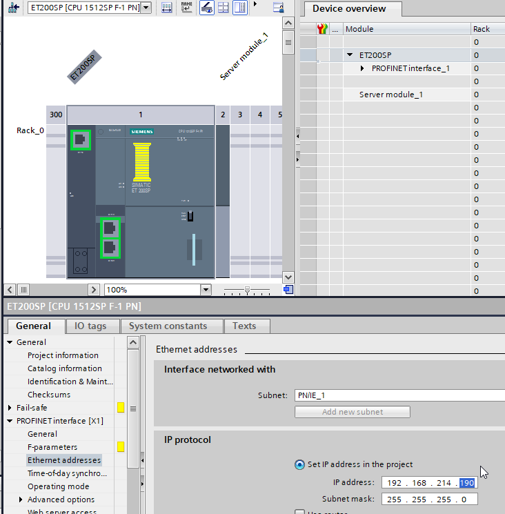
a. Devices & networks -> Device overview: Do the used Hardware modules match those in the TIA project? (Article number, firmware version)

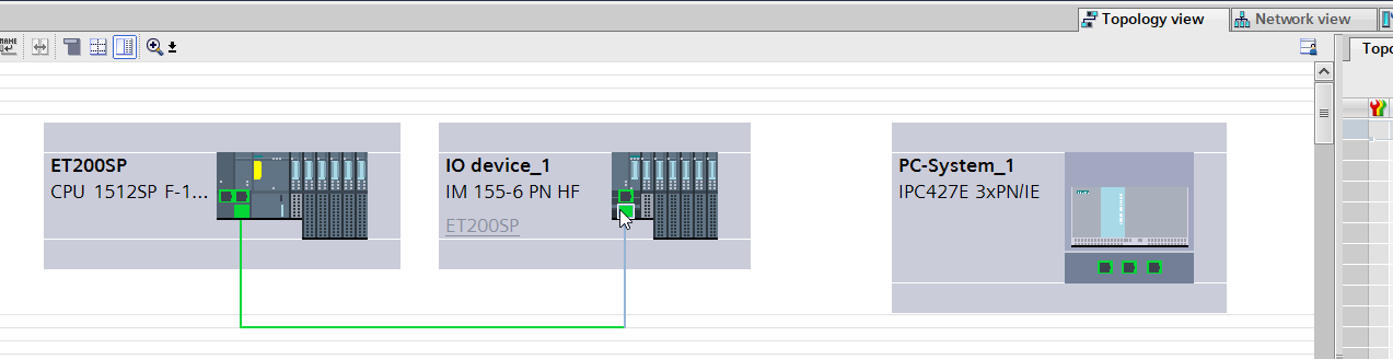
b. Devices & networks: Topology view: Are the ports connected correctly? (No deviations are allowed here)
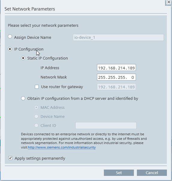
c. Online accesses -> Display reachable nodes -> Network Analysis: Do the IP addresses and PROFINET names of the reachable network nodes match those projected in the TIA project?
Projected IP configuration (Device -> Properties -> PROFINET interface [X1]):
3. Adjust Hardware configuration
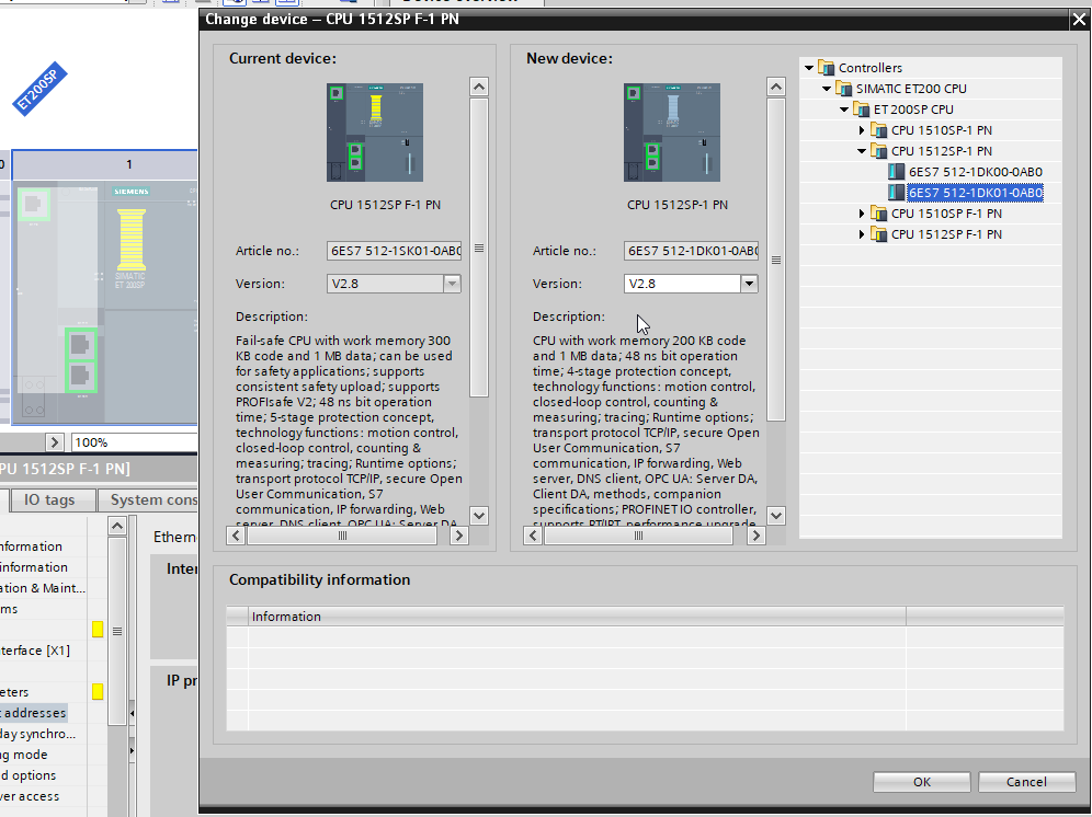
a. Project the correct devices and firmware versions
b. Adjust wiring if ports do not match those in the project
c. Adapt IP addresses and PROFINET names of the accessible nodes to TIA project
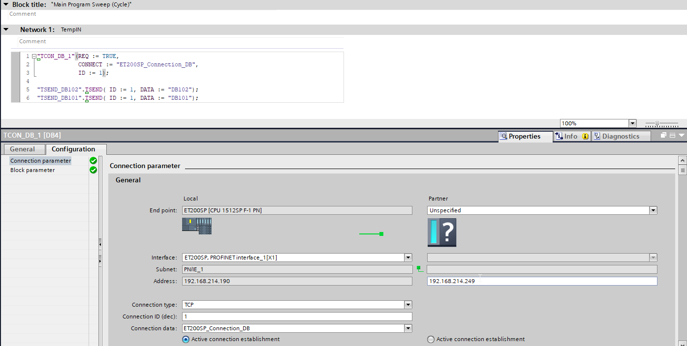
4. Configure IP address of data transmission in Main [OB1] -> TCON_DB_1
(IP address of connection partner needs to be the Edge’s IP address)
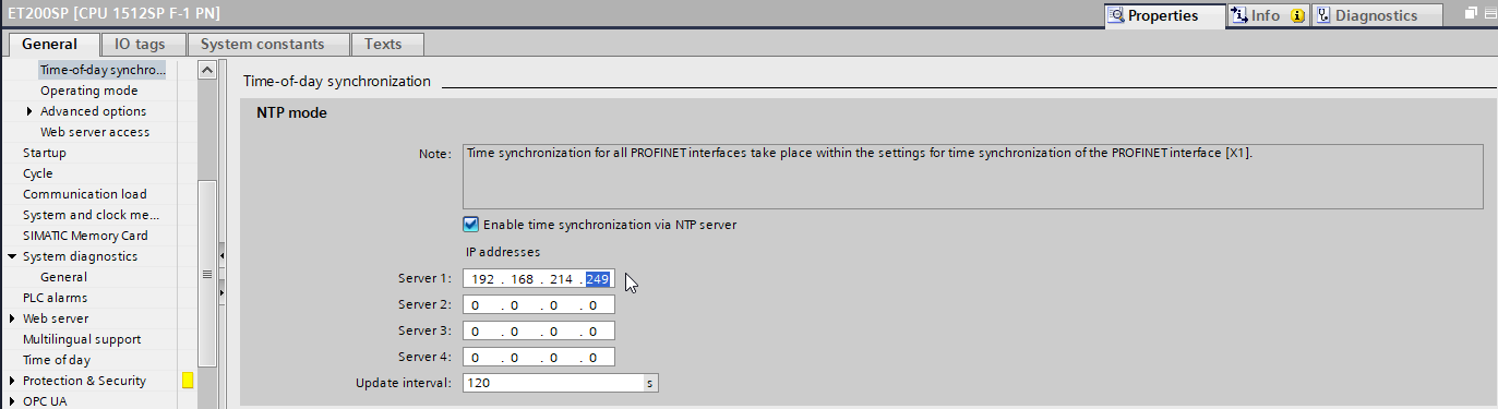
5. Select IP address of NTP time server in ET 200SP Properties Time-of-day synchronization
(Server 1 needs to contain the Edge’s IP address)
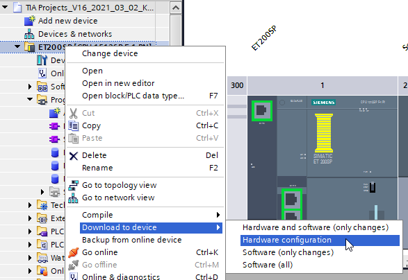
6. Compile software and hardware
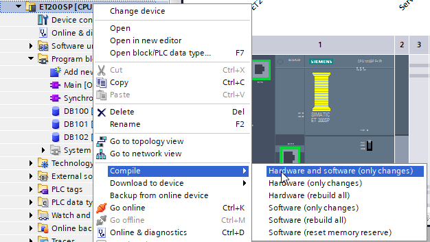
7. Load hardware configuration into controller
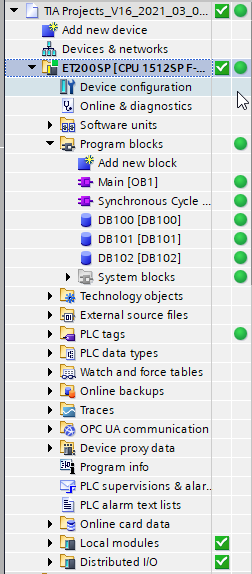
8. Go online and check if all devices are error free
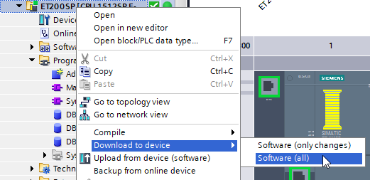
9. Load software into controller
NTP setup on the NCU
To record synchronized data, all devices need to share a common system time. Therefore, the Edge Box hosts a NTP server application. If you use a PCU to operate the NCU, use the WinSCP application to access the described files. To enable the time server synchronization on the NCU, you can use the following steps:
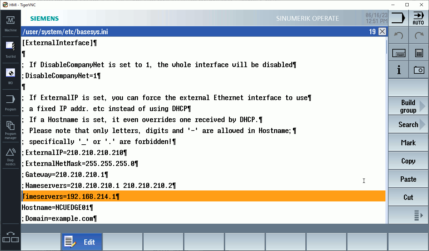
1. Go to Setup -> System data -> System CF-Card -> user -> system -> etc -> basesys.ini and open it. (WinSCP path: card/user/system/etc/basesys.ini)
2. Remove the semicolon character in front of the entry FirewallOpenPorts= "TCP/5900 TCP/102" and add the port for the timeserver (UDP/123)
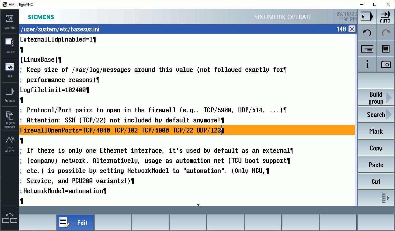
3. Add the IP address of the NTP time server (Edge’s IP address)
4. Restart the NCU and check the status of the time server connection (Setup -> HMI -> Date Time)
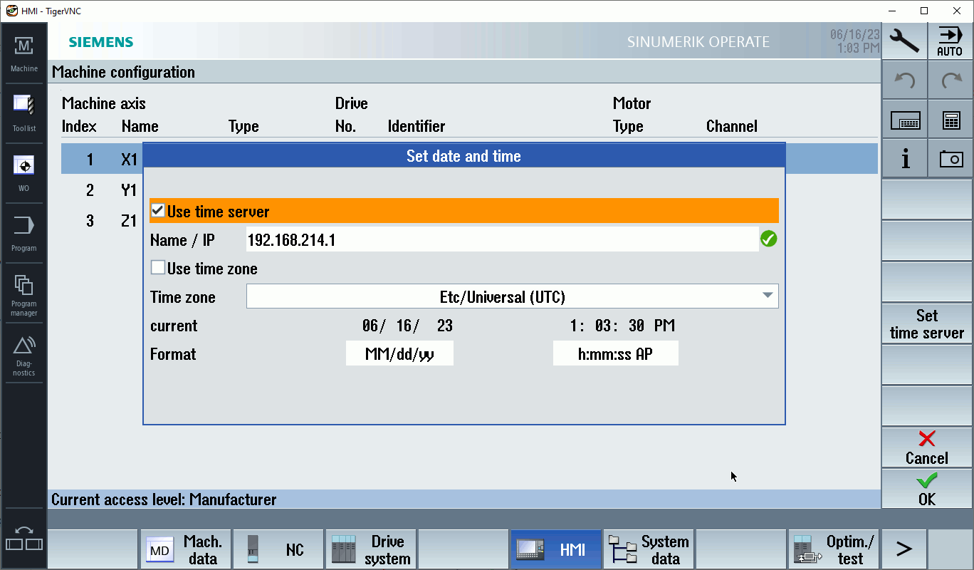
Warning: Make sure that the time synchronization is active. Green checkmark if active, red X if inactive.
Note: This option is not available on the PCU
5. If the time server is active, proceed with the Indapp checkup
Indapp checkup
Procedure
To check if all indapps are running without errors, the following steps can be performed:
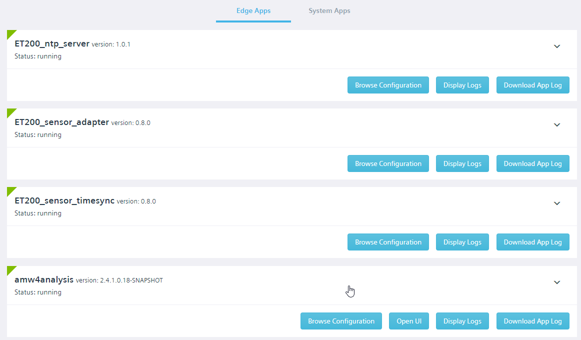
1. Check whether all applications are running in the diagnostics UI
(Local Diagnostics Application UI: https://\<box ip>:5443/diag) under App Management
2. The app logs can also be checked here (Display Logs)
App Logs
a. ET200_sensor_adapter
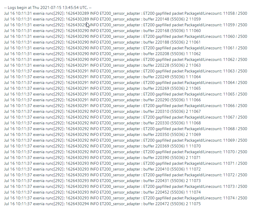
Note: The log may look different based on the actual adapter version installed. Warning: Depending on the size of the log, even longer loading times should be expected.
b. ET200_ntp_server
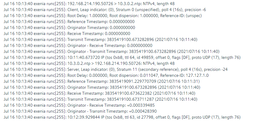
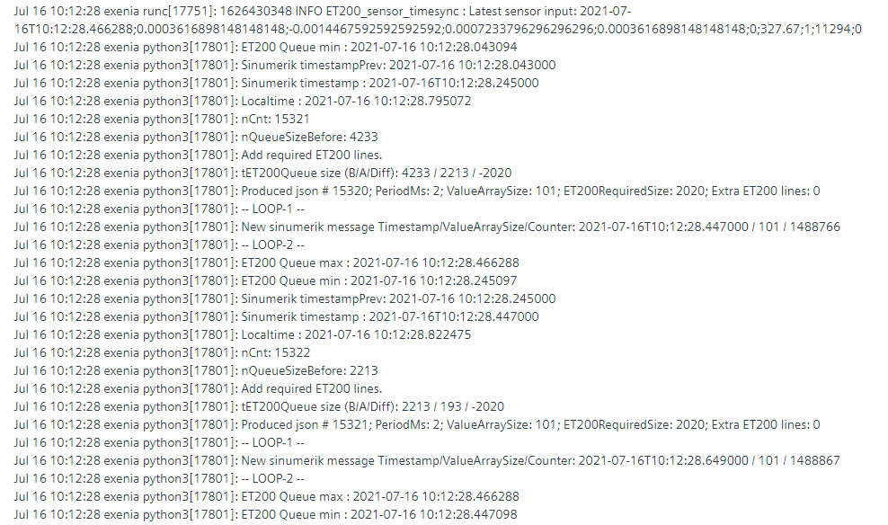
c. ET200_sensor_timesync
Error Handling
The apps require a lot of memory due to the large amounts of data. It may happen that the memory of one of the devices fills up and this leads to failure of the Sensor Adapter.
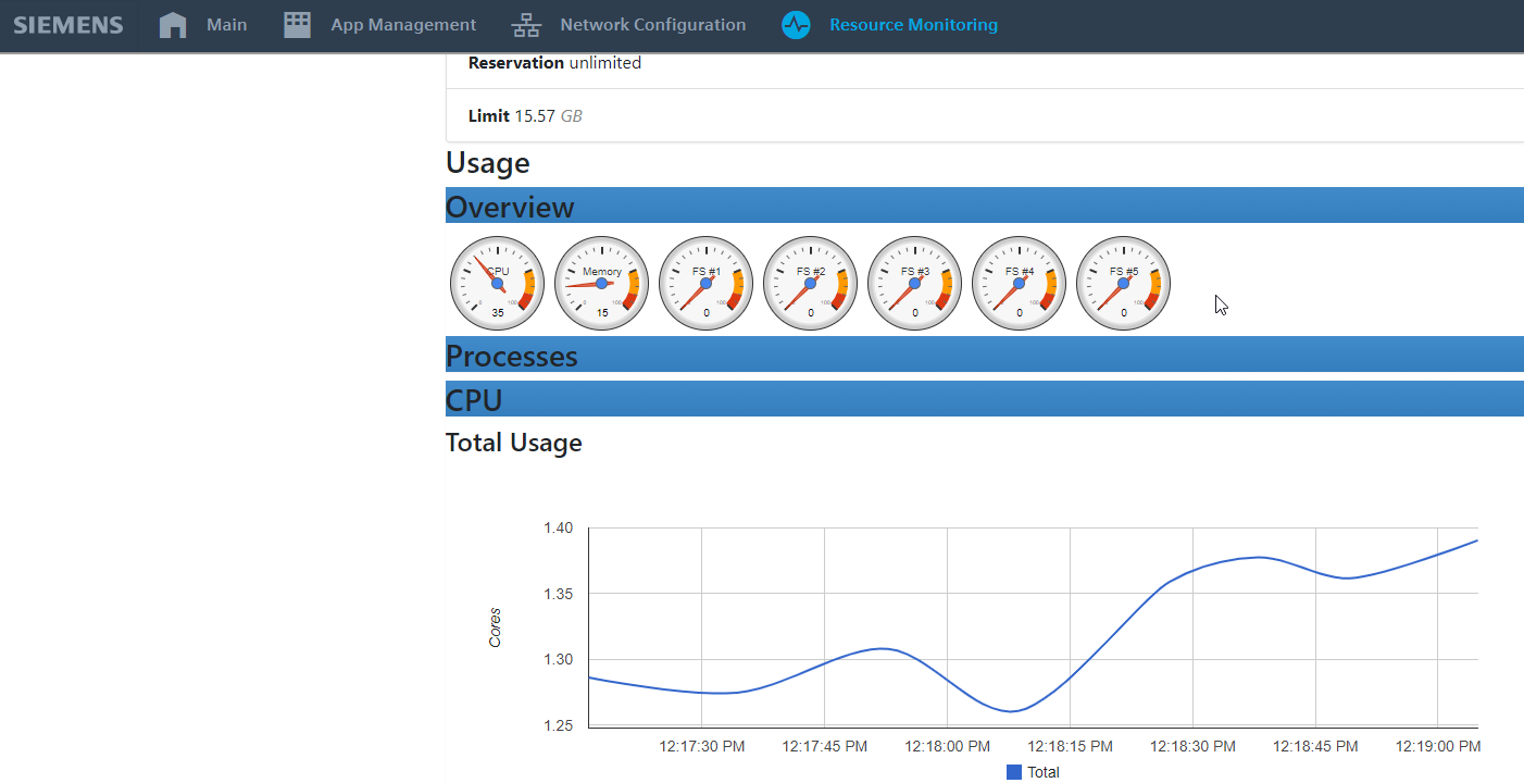
a. Check the system load of the Edge Box in the Local Diagnostics Application under Resource Monitoring
(high system loads can possibly result in errors, selection of a more powerful IPC (e. g. IPC 427E) is recommended).
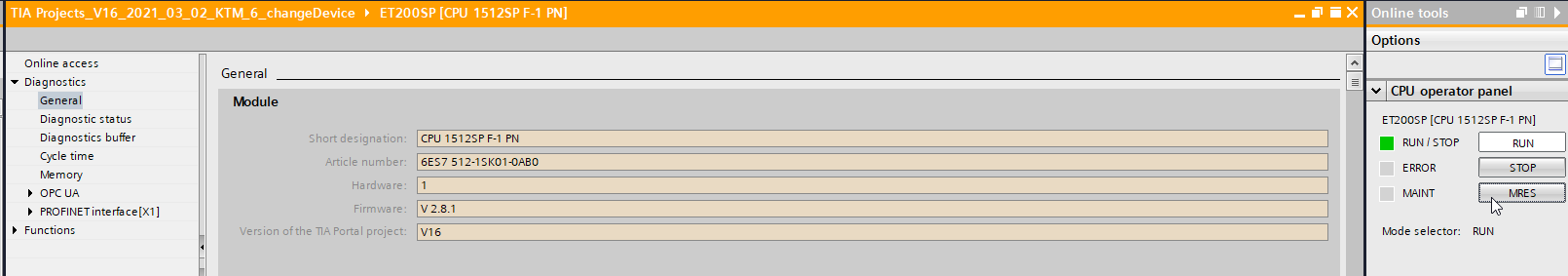
b. - Memory Reset (MRES) of the PLC via TIA Portal: ET200SP -> Online & diagnostics -> Online tools
(after MRES you have to press the RUN button to start the CPU)
If all indapps are working as described, you can continue with the configuration of a test job for data recording.
Output
The ET200_sensor_timesync application receives data from ET200 Sensor Adapter (CSV) and Sinumerik Adapter (JSON) and merges data from these sources. It assures that the time matching ET 200SP data are added to Sinumerik data. It sends the merged data in JSON format defined by Analyze My Workpiece /Capture4Analysis application via Databus. The Sinumerik Adapter JSON output (for further reference please check the Sinumerik Adapter documentation) has been extended with ET 200SP data.
The way of the extension is explained in the next JSON sample :
{
"header" : {
"message_type" : "dataobject",
"key" : "dataobject",
"source_id" : "Sinumerik_adapter_840Dsl"
},
"body" : {
"datapoint" : [
{
"address" : "CYCLE",
"timestamp" : "2018-01-15T12:48:11.322492Z",
"quality_mode" : "high_performance",
"period_ms" : 2,
"content" : [
{ "value" : [ 16581, 16582, 16583, 16584, … ] } ]
},
{
"address" : "DES_POS|1",
"timestamp" : "2018-01-15T12:48:11.322492Z",
"quality_mode" : "high_performance",
"period_ms" : 2,
"content" : [
{ "value" : [ 98.44825, 98.51608, 98.58368, 98.65108, … ] } ]
},
...
{
"address" : "DES_POS|8",
"timestamp" : "2018-01-15T12:48:11.322492Z",
"quality_mode" : "hf",
"period_ms" : 2,
"content" : [
{ "value" : [ 472252.61801, 472329.41801, 472406.21801, 472483.01801,… ] } ]
},                                             * * *
],
"high_performance_event" : [
{
"description": "PROGRAM# CH1: tick=22809391 seekOffset=4 laBuf=8 tool=0(0) ipoGC=G0 \"$A_OUT[4]=0\"", "column_index": 47
},
"description" : "PROGRAMCH1: tick=16581 seekOffset=1094 laBuf=255 tool=0(103) ipoGC=G1 \"N1093 X122.859 Y-4.002 A-94.601 B=DC(304.662) \"", "column_index" : 0
} ]


< ET200_sensor_timesync application INSERTS HERE datapoint EXTERNAL with ET 200SP data >

}}
Datapoint EXTERNAL usually contains as many value arrays as other datapoints individual values. The number of lines in value arrays depends on parameter "period_ms": 2 and ET 200SP data sampling rate (10 kHz = 10 samples/millisecond). That means there are 20 lines in an array in this example.
{
"address" : "EXTERNAL",
"timestamp" : "2018-01-15T12:48:11.322492",
"quality_mode" : "hf",
"period_ms" : 2,
"meta": "timestamp;a1ch1;a1ch2;a2ch1;a2ch2;D1;T1;DBID;PackageID;Source",
"content" : [
{ "value" :  [
[" 2018-01-15T12:48:11.322500;-2.171585648148148;0.9067563657407407;2.540147569444444;-4.1814959490740735;1;18.88;20000;473731;0",
" 2018-01-15T12:48:11.322600;-1.8543836805555554;0.8991608796296295;2.4877025462962963;-4.237919560185185;1;18.88;20000;473731;0",
 ... ],
[" 2018-01-15T12:48:11.324500;3.9706307870370368;0.6752748842592592;1.4854600694444444;-5.483579282407407;1;18.88;20000;473731;0",
" 2018-01-15T12:48:11.324600;4.259259259259259;0.6647858796296295;1.4015480324074074;-5.546875;1;18.88;20000;473731;0",
 ...   ],
...
[" 2018-01-15T12:48:11.522500;9.938151041666666;0.19133391203703703;1.1056857638888888;-8.084852430555555;1;18.88;20000;473731;0",
" 2018-01-15T12:48:11.522600;9.908854166666666;0.17939814814814814;1.1603009259259258;-8.143446180555555;1;18.88;20000;473731;0",
 ...  ]
,[Potential extra ET200 DATA block depending on the timestamp of the next Sinumerik hf json data]
 ] } ]
}
Explanation EXTERNAL datapoint:
- "address": "EXTERNAL": defines ET200 data block
- "timestamp": "2021-05-26T12:37:01.552000",: copy of the timestamp of the original Sinumerik HF JSON message
- "quality_mode": "hf",: copy of the quality_mode of the original Sinumerik HF JSON message
- "period_ms": 2,: copy of the period_ms of the original Sinumerik HF JSON message
- "meta": "timestamp;a1ch1;a1ch2;a2ch1;a2ch2;D1;T1;DBID;PackageID;Source",: it is the format header of the messages coming from ET200 Sensor Adapter application
- timestamp: sampling timestamp of ET200 data
- a1ch1: analog input1, channel 1 converted value (Volts)
- a1ch2: analog input1, channel 2 converted value (Volts)
- a2ch1: analog input2, channel 1 converted value (Volts)
- a2ch2: analog input2, channel 2 converted value (Volts)
- D1: digital input1 (8 bits - 8 channels)
- T1: analog temperature input (degrees of Celsius)
- DBID: internal data related to data transfer from ET200 (user irrelevant)
- PackageID: internal data related to data transfer from ET200 (user irrelevant)
- Source: value 0 - original ET200 data; value 1 - lines generated by the gap-filling algorithm.
-
"content": [
{ "value" : [
[" 2018-01-15T12:48:11.322500;-2.171585648148148;0.9067563657407407;2.540147569444444;-4.1814959490740735;1;18.88;20000;473731;0",
" 2018-01-15T12:48:11.322600;-1.8543836805555554;0.8991608796296295;2.4877025462962963;-4.237919560185185;1;18.88;20000;473731;0",
 ...  ],
...
,[Potential extra ET200 DATA block depending on the timestamp of the next Sinumerik HF JSON data]
 ] } ]
}
Values block (inside content) contains all data from ET200 between the Sinumerik HF timestamps of this and the next Sinumerik message.
Example use of synchronized data produced by the ET200_sensor_timesync
Configuration of an Analyze My Workpiece /Capture4Analysis test job
The configuration of the hardware should be completed up to the present state. Now the first test job for recording process data can be started. To do this, the Analyze My Workpiece /Capture4Analysis UI is started via Open UI using the App Management in the Local Diagnostic Dashboard. Before creating the test job, the recording of external data must be activated.
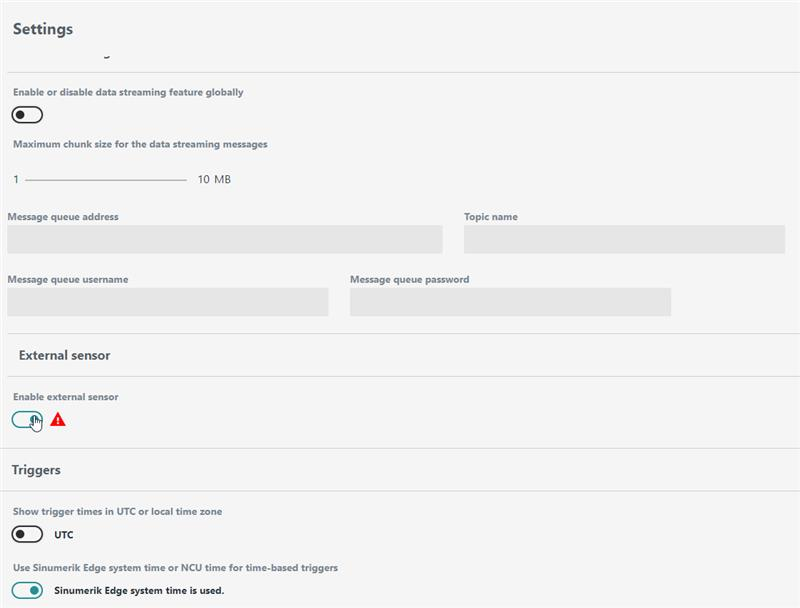
1. Open the Settings page
2. Enable External sensor slider
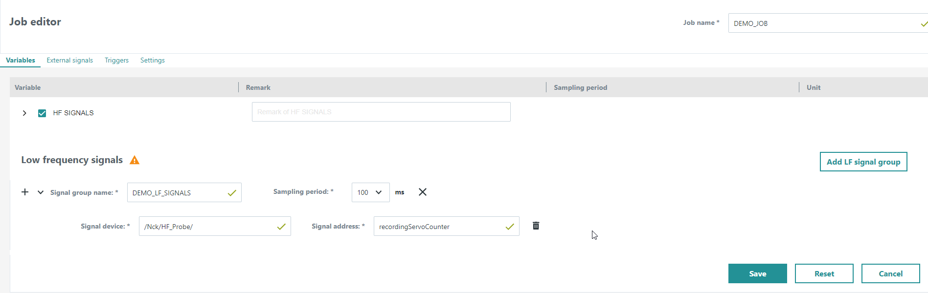
3. Open Job editor and select desired HF and LF signals
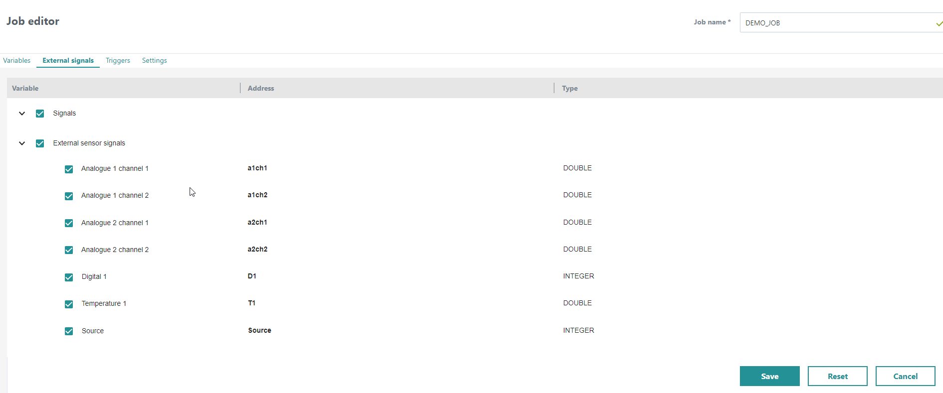
4. Switch to External signals tab and enable the needed sensor signals
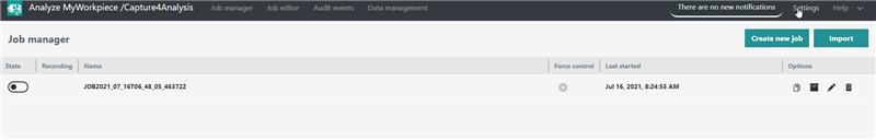
5. Activate and start test job

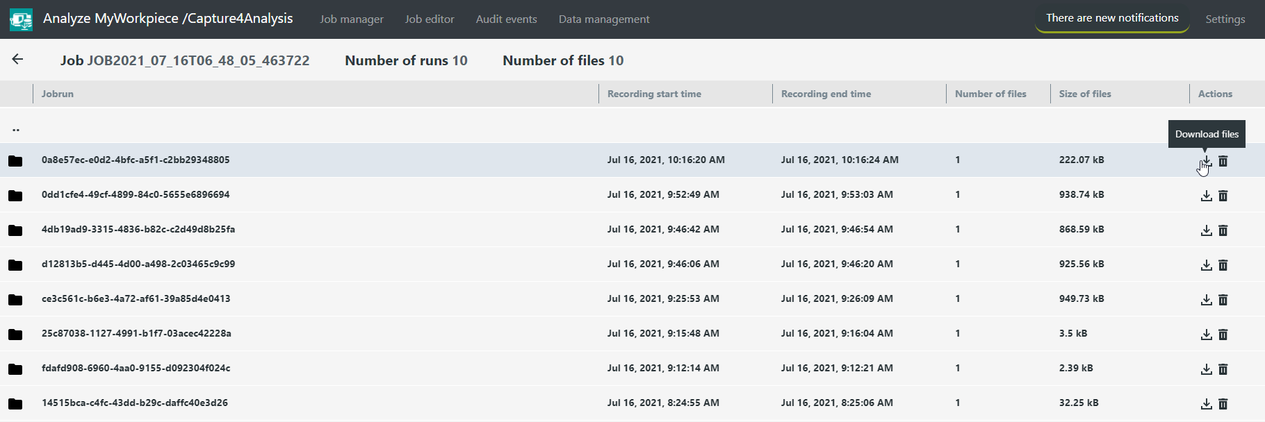
6. Stop test job and go to Data management
7. Download the job recordings
8. Open JSON file in JSON editor and check the Output Format for all the desired signals
ET200 Sensor Adapter Configurator
Introduction
The ET200 Sensor Adapter configuration is stored in a specific json file. Even though you can change the json content directly from the Insights Hub application configuration, it is strongly recommended to edit the configuration using ET200 Sensor Adapter configurator UI, which was specifically developed for this purpose. Nonetheless, for the proper setup of the adapter, gaining some knowledge about the relevant entities and fields in the corresponding json configuration file is mandatory.
Content
- Configuration fallback strategy (correlation between Insights Hub and miniweb UI configs)
- Insights Hub (IH) configuration usage + json description
- UI access via miniweb
- Configurator UI
1. Configuration fallback strategy
(correlation between Insights Hub and miniweb UI configs)
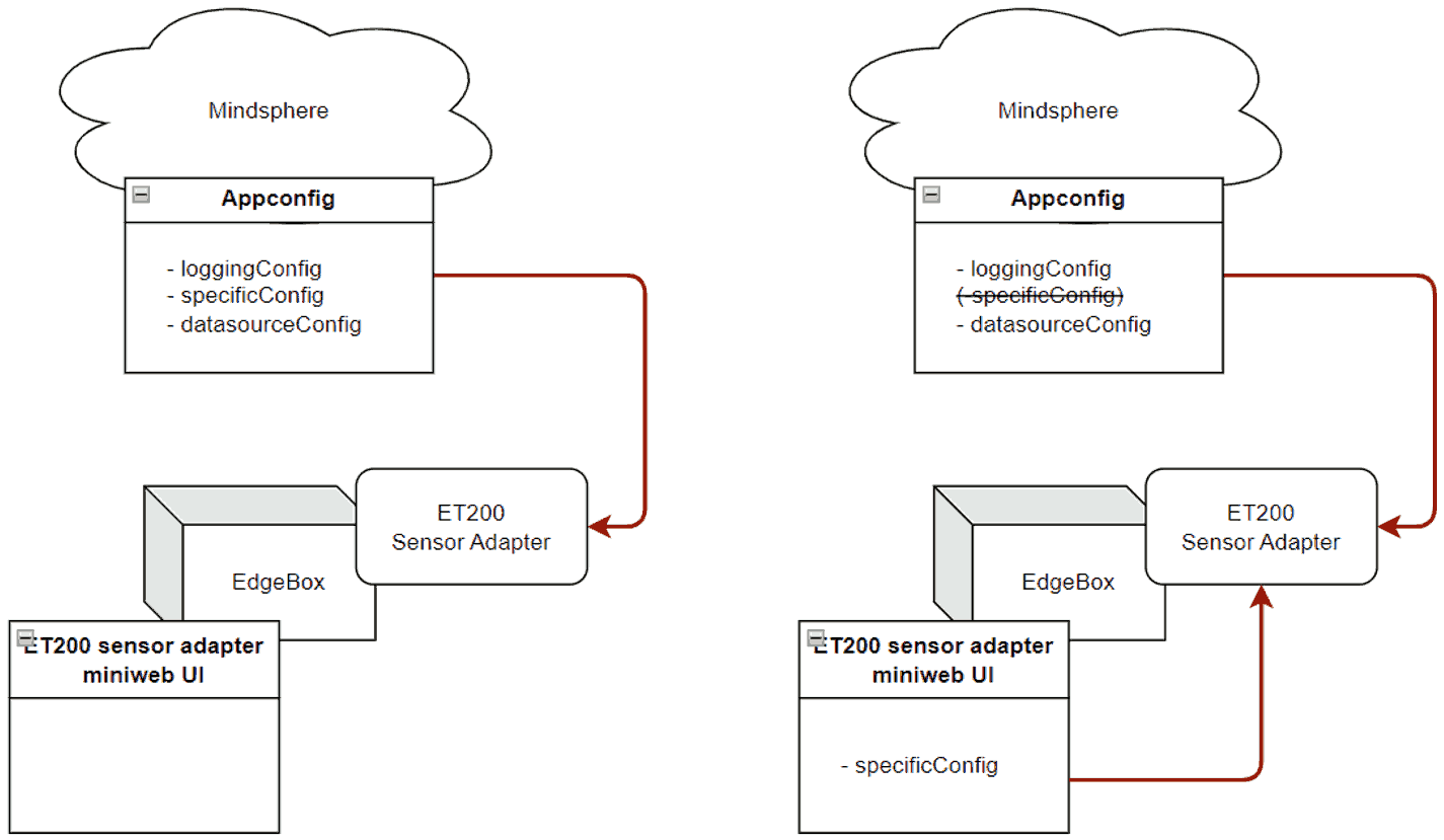
After installation and before starting ET200 Sensor Adapter, it can be configured via Insights Hub (IH).
The application launches with the IH configuration. After it is started, the specificConfig part of the IH configuration can be overridden via the ET200 Sensor Adapter Configurator User Interface (UI). The UI is reachable from the miniweb application, running on the Edgebox. After submitting the modified configuration on the UI, the application will automatically apply the changes within 2-15 seconds. Configuration changes made on the miniweb UI are saved locally on the box and do not appear in IH. Therefore, the IH configuration can not be modified via the UI. The configuration generated on the UI can be revoked (Reset button), and after resetting, the ET200 Sensor Adapter works according to the original specificConfig, stored in IH.
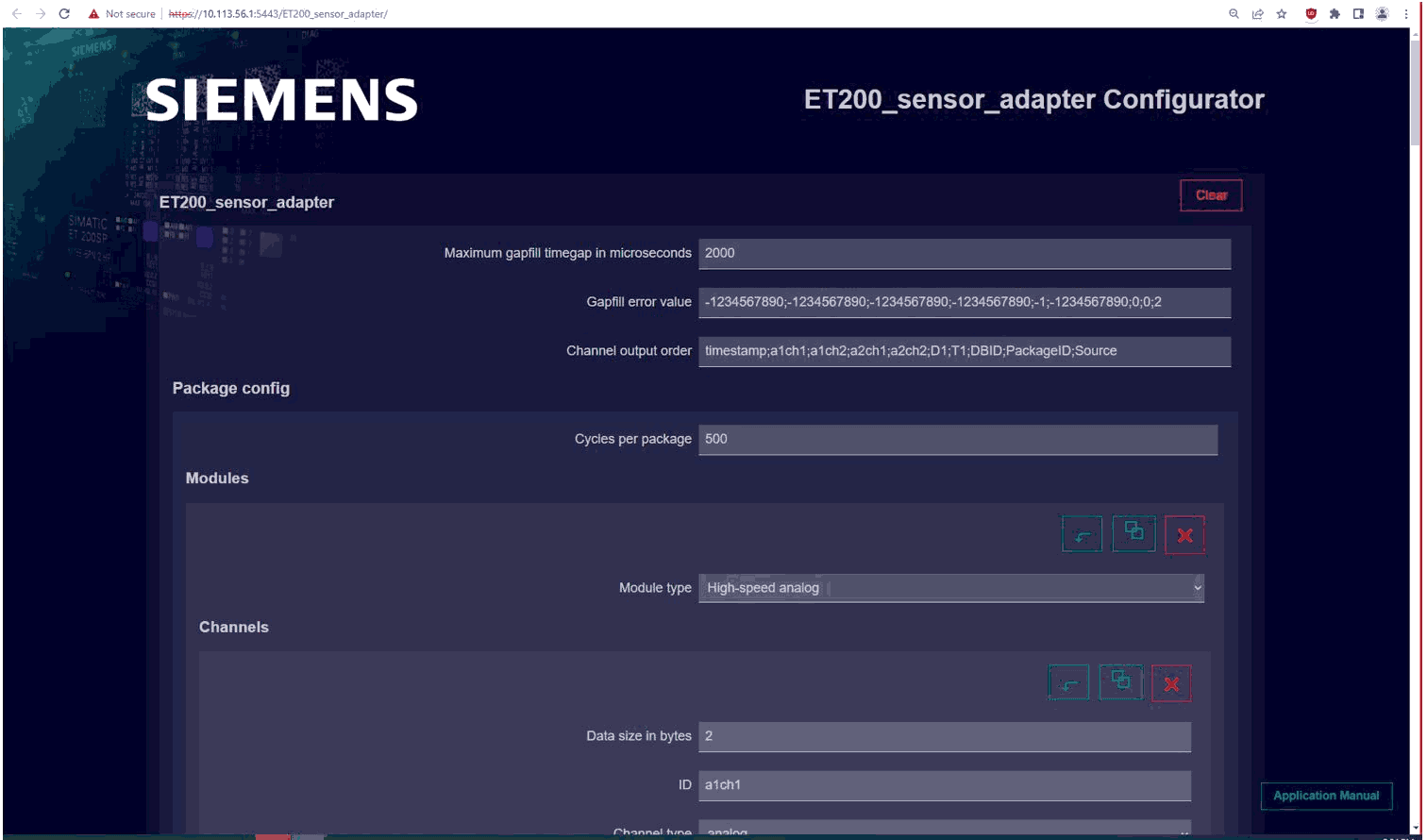
ET200 Sensor Adapter Configurator UI is available at url: https://<box ip>:5443/ET200_sensor_adapter/
Hint: the last '/' is mandatory.
 picture: configuring ET200 Sensor Adapter
2. Insights Hub configuration usage + json description
IH configuration pop-up window
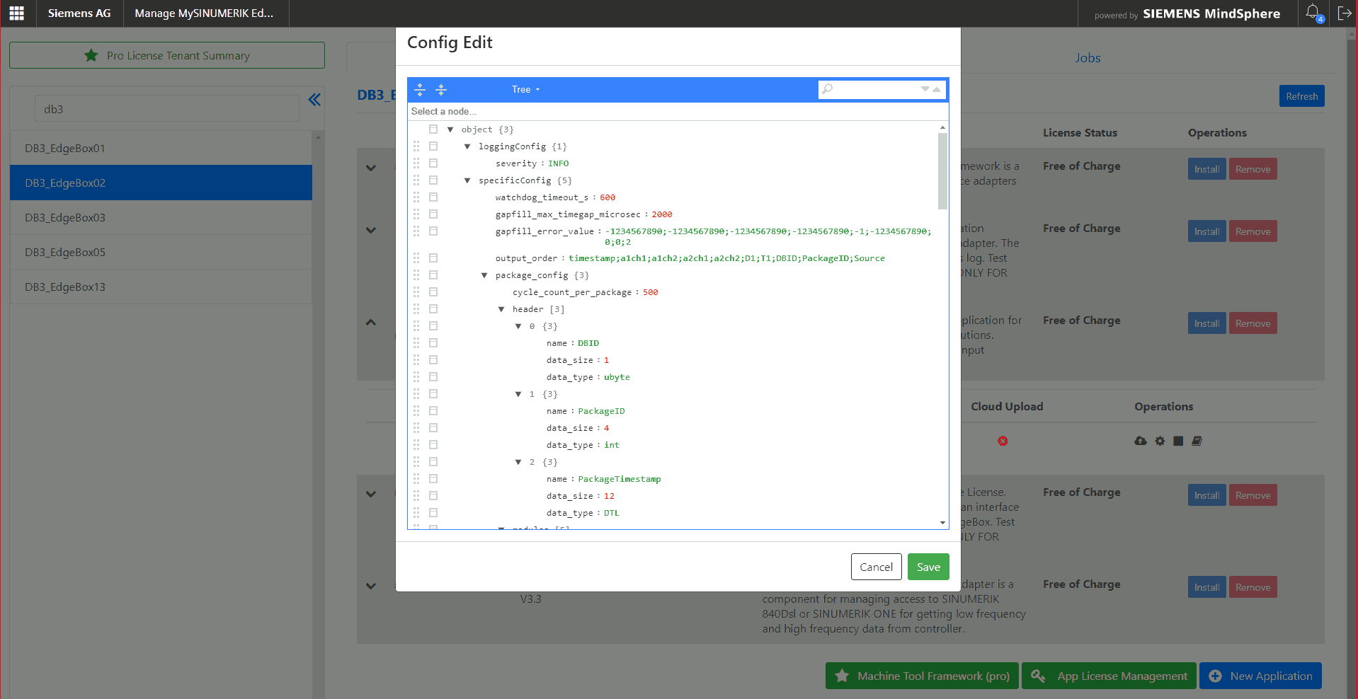 picture: IH configuration pop-up window
During the launch, the application uses the IH configuration. With the miniweb configurator UI, the specificConfig part of this configuration can be overridden in a user-friendly way and the ET200 Sensor Adapter will reconfigure itself with the modified config in runtime within 2-15 seconds.
Hint: if the
specificConfigconfiguration was set via the UI, thespecificConfigpart of the IH configuration becomes inactive, however, its content remains unchanged in IH. By pressing the Reset button on the UI, the original IH configuration is applied again in the ET200 Sensor Adapter, the local specificConfig.json is deleted by the UI. The IHspecificConfigsection is reloaded into the configurator for modification.
ET200 Sensoradapter configuration on Insights Hub
The configuration json file has 3 main parts:
1. loggingConfig
In loggingConfig the ”logCfg.severity” (more verbose/less verbose) loglevel can be set.
Note: available ”severity” values that can be set are:
DEBUG,INFO,WARN,ERROR.
2. specificConfig
It is possible to modify the entire specificConfig part on IH, according to the description of the specificConfig block in ET200 Sensor Adapter json documentation.
3. datasourceConfig
WARNING: It is recommended to leave the
datasourceConfigsection unchanged on IH and also do not clear the entirespecificConfigcontent on IH, as the application will not be able to run in these cases.
After stop/start on Insights Hub:
When ET200 Sensor Adapter is stopped and then started on the IH, the created and submitted specficConfig on the UI is not lost and it will be used. In case of reinstall on IH (stop, delete, remove, install), the UI configuration will be lost, the application will restart with the config stored on IH.
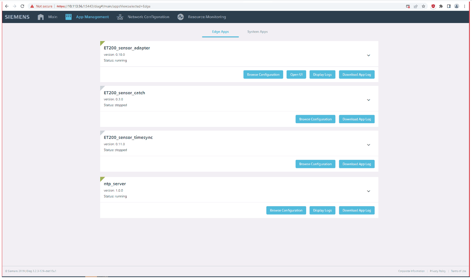
3. The miniweb UI access
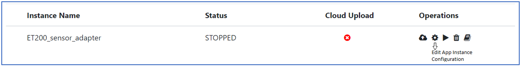
The configurator UI can be started via diagnostic interface, using the url: https://<box ip>:5443/diag/
In the main menu, choose the App Management tab, then on the loaded page’s top, click to Edge apps, and on the ET200 Sensor Adapter’s panel, the UI is reachable through the “Open UI” button. (App Management tab/Edge apps tab/ET200_sensor_adapter panel/“Open UI” button).
 picture: Diagnostic interface
In other case, the UI via the miniweb is available at url: https://<box ip>:5443/ET200_sensor_adapter/
Hint: the last '/' is mandatory).
Both cases, either with the “Open UI” button or via the miniweb, the following UI interface will greet you:
 picture: Configurator's initial page
4. Configurator UI
MAIN BUTTONS
Clear
Loads the minimal ("empty") configuration in the UI. This operation has no effect on the app, so no reconfiguration takes place until Submit button is pressed.
Reset
Deletes the local specificConfig.json file, reloads the specificConfig part of IH configuration into the UI and the ET200 Sensor Adapter will load it to the IH configuration within 2-15 seconds.
Copy
Creates the specificConfig json object, based on the content of the UI fields, and copies it to the clipboard. This can be utilized to backup the specificConfig. This can be manually added to the application's IH configuration.
Submit
Generates the specificConfig.json file based on the content of the UI fields, saves it and ET200 Sensor Adapter will load it within 2-15 seconds.
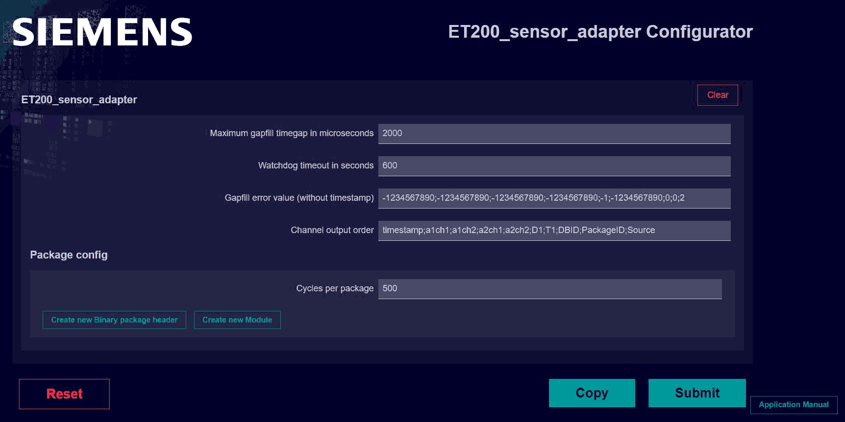 picture: Cleared Configurator with its main buttons.
SPECIFICCONFIG OVERVIEW
Hint: All these fields have a detailed description in the ET200_sensor_adapter_json documentation.
Watchdog timeout in seconds: For how long ET200 Sensor Adapter should run while it receives no data.
Maximum gapfill timegap in microseconds: Naturally, timegaps between AP timestamps vary. The ET 200SP data series may have larger gaps and they are filled in using a kind of interpolation: based on the ET 200SP device's frequency, there is a calculated ideal timegap between the consecutive AP timestamps. Larger gaps are filled up using repetition of the sensor data, however, even larger gaps, which are over Maximum gapfill timegap in microseconds, are filled up with predefined error lines (Gapfill error value).
Gapfill error value: The predefined error line in csv format that is used to fill up the timegaps larger than the value of Maximum gapfill timegap in microseconds. This line does not contain the value for the timestamp, because that is generated using primitive interpolation. Any other value can be used to define this error line, the only exception is the value associated with the Source field which must be 2.
Channel output order: The preferred order of columns of the output csv file. This section has to be consistent with the header, module and channel values.
Package Config: package_config has to describe exactly the structure described within DB101 and DB102 data block via TIA Portal.
- Cycle count per package
- Header
- Modules
- module types
- oversampling
- channels
CREATE SPECIFICCONFIG BLOCKS ON THE UI:
Header
- Create new binary package header: A new, empty header block appears on the UI, suitable to fill out its “Header name”, “Data size in bytes” and “Data type” values implicitly, according to the TIA portal settings.
Modules:
- Create new Module: A new, empty module block appears on the UI under Package config
- Create new Channel: A new, empty channel block appears on the UI under a Module
ICONS:
Hint: Hover over icon buttons to show their description.
 Up, down: Change order between items in the same category.
 Duplicate: The item, to which the button is related, will be duplicated with the same content filled in.
 Delete: The item, to which the button is related, will be deleted.
UI MANUAL:

The corresponding manual can be reached with the use of “Application Manual” button and hide with the use of “Hide Manual” button.
Any questions left?
Except where otherwise noted, content on this site is licensed under the The Siemens Inner Source License - 1.1.