Machine Tool Flow Creator
About the Machine Tool Flow Creator
The Machine Tool Flow Creator is a low-code programming environment based on the open source tool Node-RED. In the Flow Creator, it is possible to wire nodes and some of the AppSDK APIs to quickly program Edge applications and prototypes.
The Flow Creator currently supports the following services:
- Read SINUMERIK HF data
- Read and write LF data of different data sources
- Subscribe to SINUMERIK LF data (data events)
- Receive SINUMERIK high performance events
- Read data from the Edge Databus
- Upload time series data to the Insights Hub
- Provide data to the Edge-internal OPC UA Server
- Receive LF data from Edge-internal OPC UA Client
- Communicate to other Edge indapps
- Read the specific configuration section from the app configuration
- Publish event messages over the AppSDK Event Handling functionality
- Access the alarmlist from the Information Service
- Log data to the Flow Creator app log
- Build dashboards with the node-red-dashboard module
Installing and accessing the Machine Tool Flow Creator
Installing Machine Tool Flow Creator
The Machine Tool Flow Creator can be installed on the edge device like any other application. Search for machinetoolflowcreator and install it on the asset using Manage MySINUMERIK Edge /App Management.
Detailed information regarding installing process can be found here.
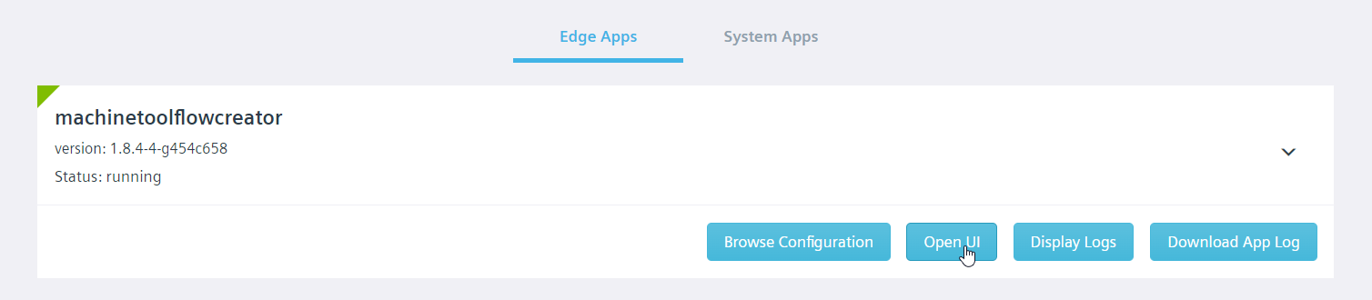
Accessing the Flow Creator Editor
After installing and starting the app instance, the browser-based Flow Creator editor can be accessed over the App Management tab of the local diagnostics dashboard.
Alternatively, the following link can be used to access the editor.
https://<host_name>:5443/machinetoolflowcreator/

Accessing the Flow Creator Dashboard UI
The Machine Tool Flow Creator comes with the Node-RED dashboard module to quickly create live data dashboards.
The dashboard UI can be accessed by the following link.
https://<host_name>:5443/machinetoolflowcreator/ui
After accessing the Flow Creator dashboard UI, you will see the following screen.

Using AppSDK Nodes
Databus Consumer Node
The Databus Consumer node is used to read data from the Databus with a given Message Name property.
Note
For consuming additional data sources, the data source configuration of Machine Tool Flow Creator should be modified as it is described here. Then a databus consumer node with a matching Message Name property can be added to the flow.
Properties
The Message Name property of the Databus Consumer node can be changed by double-clicking on the node. In order to subscribe to arbitrary Databus messages, you need to provide the Message Name property and change the app configuration using Manage MySINUMERIK Edge /App Management. More information regarding the required configuration can be found here.
Inputs
| Input | Name | Data type | Description |
|---|---|---|---|
| 1 | Trigger signal | Any | Message to trigger the node |
The Databus Consumer node is triggered by any input type and automatically registers a Databus consumer listening to the specified Message Name. It is not possible to stop the Databus Consumer node after triggering.
Outputs
| Output | Name | Data type | Description |
|---|---|---|---|
| 1 | Message data | String | Message data coming from Databus |
| 2 | Databus return code | String | Databus return code of every reading operation |
If the message data is coming from the SINUMERIK Adapter, information regarding incoming data payload format can be found here.
Databus Producer Node
The Databus Consumer node is used to write data to the Databus with a given Message ID property.
Properties
The Message ID property can be changed by double-clicking on the node. The properties window will pop up and by using this window, any other value can be assigned.
Note
The Databus Producer node currently supports two Message IDs for writing to the Databus. The first Message ID is upload2cloud which is used to send data to Insights Hub. To publish data to the Edge-internal OPC UA Server, the Message ID edge_opcua_data can be used. Other Message IDs are currently not implemented.
Inputs
| Input | Name | Data type | Description |
|---|---|---|---|
| 1 | Message data | String | Message to publish on the Databus |
This node has only one input and this input is used for supplying data to this node. When data is supplied to the input, this node writes the given data to Databus using the configured Message ID property.
Outputs
| Output | Name | Data type | Description |
|---|---|---|---|
| 1 | Databus return code | String | Databus return code of every writing operation |
Parameter Service Reader Node
This node is used for reading data using the parameter-service.
Properties
| Property | Descripiption |
|---|---|
| Datasource ID | Datasource ID for the parameter-service reading operation |
By default, the Datasource ID is SINUMERIK_NCU1. Using that ID, it is possible to read LF data (BTSS variables, PLC variables and GUD variables) from the connected SINUMERIK NCU.
Inputs
| Input | Name | Data type | Description |
|---|---|---|---|
| 1 | Variable list | Array of objects | Supply variable (list) for reading operation |
The node will trigger a parameter-service read request after receiving a valid input. One or multiple variables can be supplied to the input as an array of JSON objects with the following input format.
[
    {
        "variable_name": "/channel/parameter/r[u1,1,#1]"
    },
    {
        "variable_name": "/channel/parameter/r[u1,2,#1]"
    }
]
Note
Some adapters may not support reading multiple parameters at the same time. Please check the adapter-related documentation to see the supported methods. If multi parameter read is not supported, you can use single parameter read by passing the input as a single object instead of an array - e. g.: { "variable_name": "/channel/parameter/r[u1,1,#1]" }.
Outputs
| Output | Name | Data type | Description |
|---|---|---|---|
| 1 | Read data | Object | Read data returned from the data source |
| 2 | Error message | Object | Error message of the reading operation |
| 3 | Return code | Object | Return code of the reading operation |
Parameter Service Reader Output 1 - Read data
This output returns the message after a successful reading operation. The returned message has a similar structure to the input. The output objects are extended by the result property, which contains the read parameter value(s) and the data type.
Sample read data output
[
    {
        "variable_name": "/channel/parameter/r[u1,1,#1]",
        "result":
        [
            {
                "value": "25",
                "type": 10
            }
        ]
    },
    {
        "variable_name": "/channel/parameter/r[u1,2,#1]",
        "result":
        [
            {
                "value": "5",
                "type": 10
            }
        ]
    }
]
Parameter Service Reader Output 2 - Error Message
This output is not triggered after a successful operation. In case of an error, the error message can be accessed from this output.
Sample error message
{
    "errorMessage": "The SINUMERIK Adapter cannot connect to the control unit."
}
Parameter Service Reader Output 3 - Return Code
This output is triggered after each execution of the node. For a successful reading request, it returns 0. In case of an error, it returns a return code related to specific error case from the parameter-service layer.
{
    "returnCode": 0
}
More detailed information regarding SINUMERIK Adapter-related parameter-service return codes can be found here.
Parameter Service Writer Node
This node is used for writing data using the parameter-service.
Properties
| Property | Description |
|---|---|
| Datasource ID | Datasource ID for the parameter-service writing operation |
By default, the Datasource ID is SINUMERIK_NCU1. Using that ID, it is possible to change LF data values (BTSS variables, PLC variables and GUD variables) of the connected SINUMERIK NCU.
Inputs
| Input | Name | Data type | Description |
|---|---|---|---|
| 1 | Variable list | Array of objects | Supply variable (list) for writing operation |
Sample input format
[
    {
        "variable_name": "/channel/parameter/r[u1,1,#1]",
        "variable_type": 10,
        "variable_value": "100"
    },
    {
        "variable_name": "/channel/parameter/r[u1,2,#1]",
        "variable_type": 10,
        "variable_value": "80"
    }
]
Outputs
| Output | Name | Data type | Description |
|---|---|---|---|
| 1 | Error message | Object | Error message of the writing operation |
| 2 | Return code | Object | Return code of the writing operation |
Parameter Service Writer Output 1 - Error message
This output is not triggered after a successful operation. In case of an error, the error message can be accessed from this output.
Sample error message
{
    "errorMessage": "The SINUMERIK Adapter cannot connect to the control unit."
}
Parameter Service Writer Output 2 - Return code
This output is triggered after each execution of the node. For a successful writing request, it returns 0. In case of an error, it returns a return code related to specific error case from the parameter-service layer.
{
    "returnCode": 0
}
More detailed information regarding parameter-service return codes can be found here.
Specific Config Reader Node
This node is used to read the specific config section of the application configuration.
Inputs
| Input | Name | Data type | Description |
|---|---|---|---|
| 1 | Trigger signal | Any | Message to trigger the node |
The Specific Config Reader node is triggered by any input type.
Outputs
| Output | Name | Data type | Description |
|---|---|---|---|
| 1 | Read specificConfig section | Object | Read entry of the application configuration |
| 2 | Return code | Object | Return code of the reading operation |
Specific Config Reader Output 1 - Read specificConfig section
This output returns the entry of the section after a successful reading operation. The returned message has the similar structure as within the application configuration.
Sample read data output
{
  "specificArray": [
    "item0",
    "item1",
    "item2"
  ],
  "specificDecimal": 10,
  "specificString": "sample value"
}
Specific Config Reader Output 2 - Return Code
This output is triggered after each execution of the node. For a successful reading request, it returns 0. In case of an error, it returns 1.
{
  "returnCode": 0
}
Publish Event Node
This node is used for publishing events to other Edge apps using the Event Manager interface.
Properties
| Property | Descripiption |
|---|---|
| Destination app | Name of the target app to receive the event |
| Event name | Name of the event, that shall be triggered on the destination app |
Inputs
| Input | Name | Data type | Description |
|---|---|---|---|
| 1 | Message data | String | Event message to be published |
This node has one input and is used for supplying data to this node. When data is supplied to the input, this node publishes it to the specific destination application as an event message with the given event name.
Outputs
| Output | Name | Data type | Description |
|---|---|---|---|
| 1 | Result message | String | Result message containing success or error information |
The result message contains the information for success or error and also the application name and event name.
"Success publishing AddNode to opcuaserver"
Alarm List Reader Node
The SinumerikAdapter provides status information of a connected SINUMERIK device by implementing an information service. This node is used for reading the Alarm List from the information service.
Properties
| Property | Descripiption |
|---|---|
| Datasource ID | Datasource ID for the parameter-service reading operation |
By default, the Datasource ID is SINUMERIK_NCU1. Using that ID, it is possible to read the alarm list from the connected SINUMERIK NCU.
Outputs
| Output | Name | Data type | Description |
|---|---|---|---|
| 1 | Alarm List | Object | Alarm List coming from the information service |
| 2 | Return code | Object | Return code of the reading operation |
Alarm List Reader Output 1 - Message Data
This output is triggered after each execution of the node. The returned object contains one alarmObject for every alarm in the SINUMERIK's alarm list.
More detailed information regarding the schema can be found here.
Alarm List Reader Output 2 - Return Code
This output is triggered after each execution of the node. For a successful reading request, it returns 0. In case of an error, it returns a return code related to specific error case from the parameter-service layer.
{
    "returnCode": 0
}
Logger Node
The Logger node is used for the AppSDK logging functionality. This node has no outputs.
Properties
| Property | Description |
|---|---|
| Severity | Severity level of logger node |
| Appender | Appender type of logger node |
Inputs
| Input | Name | Data type | Description |
|---|---|---|---|
| 1 | Logging message | String | Message string to be logged |
Samba File Reader Node
Properties
| Property | Description |
|---|---|
| Exclusive | Opens the file in exclusive mode. |
Exclusive mode, when enabled, means that the file has to be opened by a single entity, globally. If the file is already open by some other entity, operation will fail.
Inputs
| Input | Name | Data type | Description |
|---|---|---|---|
| 1 | File path | String | Path of the file to read. |
Sample input format
{
  "payload": {
    "path": "/file-to-read"
  }
}
Outputs
| Output | Name | Data type | Description |
|---|---|---|---|
| 1 | Success | Object | The input message is forwarded to this output on success. |
| 2 | Error | Object | Exception object is forwarded as payload. |
Samba File Writer Node
Properties
| Property | Description |
|---|---|
| Create | Creates the file if it does not exist. |
| Append | Opens the file in append mode. |
| Truncate | Erases the contents of the file before writing. |
| Exclusive | See Samba File Reader node. |
Create flag, when enabled, will create the file if it does not exist.
Append flag moves the cursor to the end of the file after opening, written data will get appended at the end of the file.
Truncate flag erase the contents of the file before writing to it. I.e. when truncate and append is not enabled, writing new data will overwrite the data at the beginning of the file but will not erase the following data after the written amount.
Inputs
| Input | Name | Data type | Description |
|---|---|---|---|
| 1 | File path | String | Path of the file to write. |
| 2 | Data | String or TypedArray | Data to write to the file. |
Sample input format
{
  "payload": {
    "path": "/file-to-write",
    "data": "hello world",
  }
}
Outputs
| Output | Name | Data type | Description |
|---|---|---|---|
| 1 | Success | Object | The input message is forwarded to this output on success. |
| 2 | Error | Object | Exception object is forwarded as payload. |
Samba File Deleter Node
Inputs
| Input | Name | Data type | Description |
|---|---|---|---|
| 1 | File path | String | Path of the file to delete. |
Sample input format
{
  "payload": {
    "path": "/file-to-delete"
  }
}
Outputs
| Output | Name | Data type | Description |
|---|---|---|---|
| 1 | Success | Object | The input message is forwarded to this output on success. |
| 2 | Error | Object | Exception object is forwarded as payload. |
Samba Directory Creator Node
Inputs
| Input | Name | Data type | Description |
|---|---|---|---|
| 1 | Directory path | String | Path of the directory to create. |
Sample input format
{
  "payload": {
    "path": "/new-directory"
  }
}
This node creates a directory on the given path. Parent directories must exist, otherwise an error will be generated. Likewise, an error will be generated if the directory already exists.
Outputs
| Output | Name | Data type | Description |
|---|---|---|---|
| 1 | Success | Object | The input message is forwarded to this output on success. |
| 2 | Error | Object | Exception object is forwarded as payload. |
Samba Directory Lister Node
Inputs
| Input | Name | Data type | Description |
|---|---|---|---|
| 1 | Directory path | String | Path of the directory to list the contents of. |
Sample input format
{
  "payload": {
    "path": "/my-directory"
  }
}
Outputs
| Output | Name | Data type | Description |
|---|---|---|---|
| 1 | Success | Object | Payload contains a list of entries. |
| 2 | Error | Object | Exception object is forwarded as payload. |
This node lists the file on a given directory in payload.path. The given path must be a directory and must exist, otherwise an error will be generated.
The entries in the successful output payload has the following format:
{
  "name": "string", // name of the entry,
  "type": "string" // one of "file", "directory" or "unknown"
}
Sample success output format
{
  "payload": [
    {
      "name": "name-of-the-entry",
      "type": "file"
    }
  ],
  "other-input-data": {

  }
}
Samba Directory Deleter Node
Properties
| Property | Description |
|---|---|
| Recursive | Attempts to recursively delete the given directory. |
| Check | Generate an error if the given directory does not exist. |
Recursive flag, when enabled, tries to recursively remove the contents of the directory.
Check flag, when disabled, will prevent generating an error if the given directory does not exist. Also, when recursive flag is enabled, the same principle applies to sub-directories and files as well, in case they get removed by some external factor during iteration and removal.
Inputs
| Input | Name | Data type | Description |
|---|---|---|---|
| 1 | File path | String | Path of the file to write. |
| 2 | Data | String or TypedArray | Data to write to the file. |
Sample input format
{
  "payload": {
    "path": "/file-to-write",
    "data": "hello world",
  }
}
Outputs
| Output | Name | Data type | Description |
|---|---|---|---|
| 1 | Success | Object | The input message is forwarded to this output on success. |
| 2 | Error | Object | Exception object is forwarded as payload. |
Update running flow in Machine Tool Flow Creator
The Machine Tool Flow Creator starts by default with a sample flow to demonstrate some of its features.
The active flow can be updated in two ways.
- Update flow locally using the Flow Creator editor
- Update flow from Manage MySINUMERIK Edge /App Management
Update flow locally using Flow Creator Editor
By default, Flow Creator flow can be updated locally from Flow Creator editor and these changes are remanently. That means, they are active even after a reboot.
Note
Please note that the specificConfig>updateFlow flag of the app configuration should be false. Otherwise a new flow will be downloaded from the configuration and overwrite the local flow.
Updating Flow from Manage MySINUMERIK Edge /App Management
It is also possible to update the running flow from Manage MySINUMERIK Edge /App Management remotely. To do that, the specificConfig section of the app configuration needs to be edited.
- The specificConfig>updateFlow flag should be set to true to update the running flow from configuration file.
- Insert the new flow in the specificConfig>runningFlow property in base64 encoding. This flow will be downloaded and activated, if the updateFlow flag is set true.
| updateFlow Property | Behavior |
|---|---|
| true | Local flow will be overwritten by specificConfig/runningFlow |
| false | Local flow will be persisted, local changes will be persisted. |
For more information regarding changing the configuration of installed app instances please refer here.
Sample section of the app configuration
    "specificConfig": {
      "runningFlow":  ["W3siaWQiOiJiYmNhODUwMC42YWZkODgiLCJ0eXBlIjoidGFiIiwibGFiZWwiOiJTYW1wbGUgQXBwU0RLIEZsb3ciLCJkaXNhYmxlZCI6ZmFsc2UsImluZm8iOiIifV0K"],
      "updateFlow": true
    }
Application Examples
The Machine Tool Flow Creator comes with five sample flows to demonstrate some of its features. The flows can be found in the folder Menu > Import > Local.
Sample Flow 1 - HF and LF Data Dashboard
The first sample flow 1_DataDashboard.json demonstrates how to continuously read SINUMERIK HF and LF data and how to interact with the SINUMERIK control by writing variables using the parameter-service. It contains several nodes of the Node-Red dashboard to visualize HF and LF datapoints. Every two seconds, it writes a single payload back to the Databus, which is then uploaded to the Insights Hub as time series data. Finally, the Logger node is used to write incoming data and the return messages to the app log.
Warning
By deploying the flow, the R-Parameter values of R[1] and R[2] will be overwritten. Please make sure, that these parameters don't store values, which are utilized by other programs.
Use case - Quick data dashboarding
Dashboards are a powerful tool for the data exploration of process data. The node-red-dashboard module is the enabler for quick dashboarding of time series data. It can be used to visualize LF and HF datapoints, such as axis positions, currents and torques over time.
Implemented features
- Read SINUMERIK HF data
- Read data from the Edge Databus
- Read and write SINUMERIK LF data
- Upload time series data to the Insights Hub
- Log data to the Flow Creator app log
- Build dashboards with the node-red-dashboard module
Configuration
- Open the Machine Tool Flow Creator.
- Import and deploy the flow.
- Open the Flow Creator dashboard UI.
Sample Flow 2 - OPC UA Provider App
The second sample flow 2_OpcuaProvider.json contains a simple OPC UA provider application to publish data to the Edge-internal OPC UA Server using the Databus Producer node.
Use case - Implementation of OPC UA companion specifications
The OPC UA Server of the Edge helps to implement OPC UA Companion Specifications in the machine tool domain, such as: - UA4MT (OPC 40501-1 - UA CS for Machine Tools Part 1 - Monitoring and Job) - UA4CNC (OPC 40502 - UA for Computerized Numerical Control (CNC) Systems) - MTConnect (OPC 30070-1 - UA for MTConnect, Part 1: Device Model)
The Flow Creator acts as the transformation engine to fetch specific machine data, adapt it to the OPC UA Companion Specification and provide it to the OPC UA Server. This way, MES, ERP systems or other OPC UA Clients can access the standardized data.
Implemented features
- Read SINUMERIK LF data
- Provide data to the Edge-internal OPC UA Server
Configuration
To send data successfully, first a data model should be added to the configuration of the Flow Creator application. Further information regarding this step can be found in Creating a Data Model
- Open the Machine Tool Flow Creator.
- Import and deploy the flow.
- Open the machinetoolflowcreator app configuration in the Manage MySINUMERIK Edge /App Management application.
- Insert the new element opcuaserverConfig at the root level.
- Add the new element opcuaserverConfig>dataModel and insert the base64 encoded OPC UA object model.
- Save the app configuration and open the Flow Creator editor.
Sample section of the app configuration
"opcuaserverConfig": {
  "dataModel": "BASE64 encoded object model comes here"
}
"specificConfig": { ... }
}
Below, you can find a base64 encoded data model, which is used for the sample flow.
PD94bWwgdmVyc2lvbj0iMS4wIiBlbmNvZGluZz0idXRmLTgiPz4KPFVBTm9kZVNldCB4bWxuczp4c2k9Imh0dHA6Ly93d3cudzMub3JnLzIwMDEvWE1MU2NoZW1hLWluc3RhbmNlIgogICAgICAgICAgIHhtbG5zOnVheD0iaHR0cDovL29wY2ZvdW5kYXRpb24ub3JnL1VBLzIwMDgvMDIvVHlwZXMueHNkIgogICAgICAgICAgIHhtbG5zOnMxPSJodHRwOi8veW91cm9yZ2FuaXNhdGlvbi5vcmcvVGVzdFByb2plY3QvVHlwZXMueHNkIgogICAgICAgICAgIHhtbG5zOnVhPSJodHRwOi8vdW5pZmllZGF1dG9tYXRpb24uY29tL0NvbmZpZ3VyYXRpb24vTm9kZVNldC54c2QiCiAgICAgICAgICAgeG1sbnM6eHNkPSJodHRwOi8vd3d3LnczLm9yZy8yMDAxL1hNTFNjaGVtYSIKICAgICAgICAgICB4bWxucz0iaHR0cDovL29wY2ZvdW5kYXRpb24ub3JnL1VBLzIwMTEvMDMvVUFOb2RlU2V0LnhzZCI+CiAgICA8TmFtZXNwYWNlVXJpcz4KICAgICAgICA8VXJpPmh0dHA6Ly95b3Vyb3JnYW5pc2F0aW9uLm9yZy9FZGdlMkNsb3VkLzwvVXJpPgogICAgPC9OYW1lc3BhY2VVcmlzPgogICAgPEFsaWFzZXM+CiAgICAgICAgPEFsaWFzIEFsaWFzPSJCb29sZWFuIj5pPTE8L0FsaWFzPgogICAgICAgIDxBbGlhcyBBbGlhcz0iSW50MzIiPmk9NjwvQWxpYXM+CiAgICAgICAgPEFsaWFzIEFsaWFzPSJEb3VibGUiPmk9MTE8L0FsaWFzPgogICAgICAgIDxBbGlhcyBBbGlhcz0iU3RyaW5nIj5pPTEyPC9BbGlhcz4KICAgICAgICA8QWxpYXMgQWxpYXM9Ik9yZ2FuaXplcyI+aT0zNTwvQWxpYXM+CiAgICAgICAgPEFsaWFzIEFsaWFzPSJIYXNNb2RlbGxpbmdSdWxlIj5pPTM3PC9BbGlhcz4KICAgICAgICA8QWxpYXMgQWxpYXM9Ikhhc1R5cGVEZWZpbml0aW9uIj5pPTQwPC9BbGlhcz4KICAgICAgICA8QWxpYXMgQWxpYXM9Ikhhc1N1YnR5cGUiPmk9NDU8L0FsaWFzPgogICAgICAgIDxBbGlhcyBBbGlhcz0iSGFzQ29tcG9uZW50Ij5pPTQ3PC9BbGlhcz4KICAgICAgICA8QWxpYXMgQWxpYXM9IlV0Y1RpbWUiPmk9Mjk0PC9BbGlhcz4KICAgIDwvQWxpYXNlcz4KICAgIDxFeHRlbnNpb25zPgogICAgICAgIDxFeHRlbnNpb24+CiAgICAgICAgICAgIDx1YTpNb2RlbEluZm8gVG9vbD0iVWFNb2RlbGVyIiBIYXNoPSI3cnRaWWtiVm1qcjc2eFRNUzlTVzlRPT0iIFZlcnNpb249IjEuNS4yIi8+CiAgICAgICAgPC9FeHRlbnNpb24+CiAgICA8L0V4dGVuc2lvbnM+CiAgICA8VUFPYmplY3QgTm9kZUlkPSJucz0xO2k9MTAwMCIgQnJvd3NlTmFtZT0iMTpNb2RlbDEiPgogICAgICAgIDxEaXNwbGF5TmFtZT5SX3BhcmFtZXRlcnM8L0Rpc3BsYXlOYW1lPgogICAgICAgIDxSZWZlcmVuY2VzPgogICAgICAgICAgICA8UmVmZXJlbmNlIFJlZmVyZW5jZVR5cGU9Ikhhc1R5cGVEZWZpbml0aW9uIj5pPTU4PC9SZWZlcmVuY2U+CiAgICAgICAgICAgIDxSZWZlcmVuY2UgUmVmZXJlbmNlVHlwZT0iT3JnYW5pemVzIiBJc0ZvcndhcmQ9ImZhbHNlIj5pPTg1PC9SZWZlcmVuY2U+CiAgICAgICAgPC9SZWZlcmVuY2VzPgogICAgPC9VQU9iamVjdD4KICAgIDxVQVZhcmlhYmxlIERhdGFUeXBlPSJEb3VibGUiIFBhcmVudE5vZGVJZD0ibnM9MTtpPTEwMDAiIE5vZGVJZD0ibnM9MTtpPTExMDEiIEJyb3dzZU5hbWU9IjE6UjAwX1ZhcmlhYmxlIiBVc2VyQWNjZXNzTGV2ZWw9IjMiIEFjY2Vzc0xldmVsPSIzIj4gICAgICAgCgkJPERpc3BsYXlOYW1lPlIwMF9WYXJpYWJsZTwvRGlzcGxheU5hbWU+ICAgICAgIAoJCTxSZWZlcmVuY2VzPiAgICAgICAgICAKCQkJPFJlZmVyZW5jZSBSZWZlcmVuY2VUeXBlPSJIYXNUeXBlRGVmaW5pdGlvbiI+aT02MzwvUmVmZXJlbmNlPiAgICAgICAgICAKCQkJPFJlZmVyZW5jZSBSZWZlcmVuY2VUeXBlPSJIYXNDb21wb25lbnQiIElzRm9yd2FyZD0iZmFsc2UiPm5zPTE7aT0xMDAwPC9SZWZlcmVuY2U+ICAgICAgIAoJCTwvUmVmZXJlbmNlcz4gICAgICAgCgkJPEV4dGVuc2lvbnM+ICAgICAgICAgIAoJCQk8RXh0ZW5zaW9uPiAgICAgICAgICAgICAKCQkJCTxWYXJpYWJsZU1hcHBpbmc+UjBfVmFyaWFibGU8L1ZhcmlhYmxlTWFwcGluZz4gICAgICAgICAgCgkJCTwvRXh0ZW5zaW9uPiAgICAgICAKCQk8L0V4dGVuc2lvbnM+ICAgIAoJPC9VQVZhcmlhYmxlPgo8L1VBTm9kZVNldD4=
Sample Flow 3 Performance Monitor
The third sample flow 3_PerformanceMonitor.json includes a dashboard to monitor the machine productivity by displaying the overrides and the program status. Therefore, it uses the parameter-service to poll LF data from the SINUMERIK and multiple dashboard elements to display them.
Use Case - Monitor the machine productivity
The Overall Equipment Effectiveness is strongly influenced by a machine's productive time and cycle time. The Performance Monitor helps to monitor the program status and the overrides over time. With that information, it is possible to check the machine utilization and cycle times and identify optimization potentials.
Implemented Features
- Read SINUMERIK LF data
- Build dashboards with the node-red-dashboard module
Configuration
- Open the Machine Tool Flow Creator.
- Import and deploy the flow.
- Open the Flow Creator dashboard UI.
Sample Flow 4 Tool Monitor
The fourth sample flow 4_ToolMonitor.json contains a simple dashboard to display data of the equipped tool. It uses LF data subscriptions to receive the data only at value changes and dashboard nodes to display them.
Use Case - Monitor the active tool
According to studies, up to 20 % of the production costs are caused by worn tools. Therefore, it is required to monitor the production time and tool life parameters of the active tool. This sample flow provides a dashboard containing information about the active tool. It can be extended by further required tool parameters.
Implemented Features
- Read SINUMERIK LF data
- Subscribe to SINUMERIK LF data (data events)
- Read data from the Edge Databus
- Build dashboards with the node-red-dashboard module
Configuration
The flow uses SINUMERIK LF data subscriptions. The subscriptions must be configured in the Insights Hub app configuration. After configuration, a hotlink is automatically set up and a data event is triggered after every value change of the subscribed variable(s).
- Open the machinetoolflowcreator app configuration in the Manage MySINUMERIK Edge /App Management application.
- Navigate to datasourceConfig>requiredDatasource>SINUMERIK_NCU1>services>subscription-service/v1>subscriptions.
- Switch to Code view and insert the following JSON in the subscriptions array.
{ "messageId": "sinumerik_lf_data", "messageName": "toolDataChanged", "quality": "data_event", "datapoints": [ { "address": "/Tool/Catalogue/numCuttEdges[u1]" }, { "address": "/Channel/State/actTNumber[u1]" }, { "address": "/Channel/State/actToolIdent[u1]" }, { "address": "/Channel/State/actToolLength1[u1]" }, { "address": "/Channel/State/actToolRadius[u1]" } ] } - If further LF data subscriptions are needed, they can be added in the datapoints array.
- Save the app configuration.
- Open the Machine Tool Flow Creator.
- Import and deploy the flow.
- Open the Flow Creator dashboard UI.
Sample Flow 5 HF Data Logger
The fifth sample flow 5_HFDataLogger.json shows how to implement triggers for HF data capturing and logging. Therefore, high performance call events are used to start the data logging to the app log whenever a subprogram is called.
Use Case - Event-driven data capturing
For purposeful analysis of big data, it is essential to reduce the data set to interesting events, such as anomalies or process steps. This sample flow demonstrates how to use subprogram calls to trigger data capturing and logging.
Implemented Features
- Read SINUMERIK HF data
- Receive SINUMERIK high performance events
- Read data from the Edge Databus
- Log data to the Flow Creator app log
Configuration
To simulate the high performance call events, two subprogram files and one main program file must be installed on the SINUMERIK NCU.
- Access the SINUMERIK Operate and navigate to Program Manager
- Create a new part program "SAMPLEFLOW5_MAINPROGRAM.MPF" in Part programs directory.
N10 BEGIN: N20 G4F5 N30 CALL "SAMPLEFLOW5_SUBPROGRAM_1.SPF" N40 GOTOB BEGIN N50 M30 - Create a new subprogram "SAMPLEFLOW5_SUBPROGRAM_1.SPF" in Subprograms directory.
N10 G4F1 N20 CALL "SAMPLEFLOW5_SUBPROGRAM_2.SPF" N30 G4F1 N40 M17 - Create another subprogram file "SAMPLEFLOW5_SUBPROGRAM_2.SPF" in Subprograms directory.
N10 G4F5 N20 M17 - Open the main program and press the softkey Execute.
- Start the program by pressing the NC start button.
- Open the Machine Tool Flow Creator.
- Import and deploy the flow.
Hands-on tutorial series
Low-code development is a helpful tool to create your own applications on the Industrial Edge for Machine Tools platform. Discover the possibilities of the Machine Tool Flow Creator - a low-code programming environment based on Node-RED.
Episode 10a - Getting Started
Get started with the Machine Tool Flow Creator. Find out how to navigate in the environment, work with the applications examples and realize your first application on Industrial Edge for Machine Tools. The tutorial is available on YouTube and our CNC training platform CNC4you.
Covered topics
- Overview of the Machine Tool Flow Creator
- What is currently possible with the MT Flow Creator?
- Navigation in the MT Flow Creator
- Import and export flows
- Use sample flows as a template
- AppSDK nodes to use Edge APIs
Episode 10b - Working with SINUMERIK low frequency data
Discover SINUMERIK low frequency variables using the BTSS interface. In this tutorial, you will learn how to read and write PLC, GUD and NC variables and how to set user alerts on the machine tool. The tutorial is available on YouTube and our CNC training platform CNC4you.
Covered topics
- Read NC variables, PLC variables and GUD variables via BTSS
- Subscribe to value changes of low frequency variables (data events)
- Trigger a user alert by writing a PLC variable
- Build a dashboard with the node-red-dashboard module
Configuration
- Open the machinetoolflowcreator app configuration in the Manage MySINUMERIK Edge /App Management application.
- Navigate to datasourceConfig>requiredDatasource>SINUMERIK_NCU1>services>subscription-service/v1>subscriptions.
- Switch to Code view and insert the following JSON in the subscriptions array.
{ "messageId": "sinumerik_lf_data", "messageName": "programStatusChanged", "quality": "data_event", "datapoints": [ { "address": "/Channel/State/progStatus[u1,1]" } ] } - Navigate to datasourceConfig>requiredDatasource>SINUMERIK_NCU1>services>parameter-service/v1>access.
- Switch to Code view and insert the following JSON in the datapoints array.
{ "address": "DB2.DBX185.4" } - Save the app configuration.
- Switch to the SINUMERIK Operate.
- Navigate to Setup>HMI>Alarm texts>Manufacturer PLC alarm texts.
- Add the user alert with the number "700044" and the alarm text "Program execution stopped" and confirm by clicking OK.
- Restart the HMI by clicking Reboot HMI.
- Open the Machine Tool Flow Creator.
- Import and deploy the template flow.
Related links
Episode 10c - Working with SINUMERIK high frequency data
Find out about the potential of SINUMERIK high frequency data, such as motor currents or encoder positions. In this tutorial you will learn how to read high frequency data from the machine tool, calculate a moving average over the signal and to plot the data in a dashboard. The tutorial is available on YouTube and our CNC training platform CNC4you.
Covered topics
- Subscribe to high frequency data from the NCU
- Calculate the moving average for a signal
- Plot the moving average using the node-red-dashboard-module
Configuration
- Open the machinetoolflowcreator app configuration in the Manage MySINUMERIK Edge /App Management application.
- Navigate to datasourceConfig>requiredDatasource>SINUMERIK_NCU1>services>subscription-service/v1>subscriptions.
- Switch to Code view and insert the desired high frequency datapoints in the datapoints array.
{ "messageId": "sinumerik_hf_data", "messageName": "sinumerik_hf_data", "quality": "hf", "datapoints": [ { "address": "DES_POS|1" }, { "address": "CMD_SPEED|1" }, { "address":"..." } ] } - Save the app configuration.
- Open the Machine Tool Flow Creator.
- Import and deploy the flow.
Related links
- Overview of available SINUMERIK high frequency datapoints
- Configure SINUMERIK high frequency datapoints
- SINUMERIK high frequency data message format
Episode 10d - Implementing OPC UA Companion Specifications
Flexible OPC UA object models have a big potential. Learn the complete workflow to implement object models and OPC UA Companion Specifications in the Machine Tool Flow Creator. The tutorial is available on YouTube and our CNC training platform CNC4you.
Covered topics
- Workflow for an OPC UA implementation
- Create object models in Siemens OPC UA Modeling Editor
- Use function nodes to program a transformation engine in the Flow Creator
- Provide data to the Edge-internal OPC UA Server
- Watch variables in an OPC UA client (e. g. UaExpert)
Configuration
- Open the machinetoolflowcreator app configuration in the Manage MySINUMERIK Edge /App Management application.
- Insert the new element opcuaserverConfig at the root level.
- Add the new element opcuaserverConfig>dataModel and insert the base64 encoded OPC UA object model.
- Save the app configuration.
- Open the Machine Tool Flow Creator.
- Import and deploy the flow.
Related links
Any questions left?
Except where otherwise noted, content on this site is licensed under the The Siemens Inner Source License - 1.1.