Using nodes
Introduction to nodes
Definition
Nodes are configurable pieces of functionality that can process input data and produce output data. Examples range from data processing to complex functions and online services.
Categories
Visual Flow Creator palette contains set of node categories to create the flows in the working area.
It provides the following node categories:
- Basic nodes
- Input
- Output
- Industrial IoT nodes
- Function nodes
- Analytics nodes
- Storage nodes
- Array nodes
- Simple anomaly nodes
- IIoT Dashboard nodes
- Dashboard nodes
- Custom nodes
Node information
In the program user interface, you receive detailed information for each node in the info window. The info window displays the node type and the node ID for each node and other properties. The info window provides information about the exact use of the node and shows the possible applications using examples.
To view the information for a node, click the node in the "Node palette" and open the "info" tab in the info window.
Edit nodes
You can edit or change the properties of the nodes as per the configuration to execute the flow in the Visual Flow Creator.
To use a node, you must move it from the node palette to the working area using drag-and-drop.
The following table shows the various node states:
| Node states | Description |
|---|---|
| - The blue circle identifies nodes that have not yet been saved. - The red triangle indicates missing inputs or errors in the node properties. - The text below the node shows status and error messages. |
You can edit the node in the properties window, for example, to change the name of the node. Each node has its specific properties window with different setting options. To open the properties window of a node, double-click a node placed on the working area.
The following graphic shows the properties window of the "inject" node:
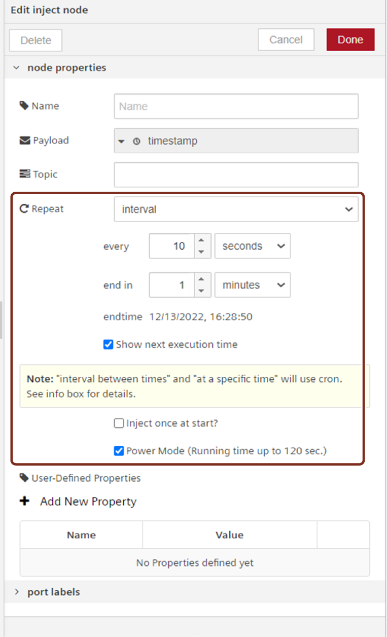
Power Mode
In this mode, the flow runs up to 120 seconds for the heavy execution and the compute hours is calculated 2.5 times more than the normal execution. This mode is available for every node which is used to trigger and msg._powerMode.
| Repeat | Description |
|---|---|
| None | In this mode, the node gets triggered only by clicking on its button. It will not be triggered automatically. |
| Interval | In this mode, the node can be configured to trigger and repeat until the specified end time. The node will be automatically terminated after reaching end time. The interval time units can be specified in seconds, minutes, hours or infinite. If required, choose "Start next execution time" parameter to display the next execution time for every execution. For example, the node can be configured to trigger at every 10 seconds with the specified end time to terminate the execution automatically. |
| Interval between times | In this mode, the node can be configured to trigger and repeat automatically in between the specified time on the specified days of the week. The interval time units can be specified in seconds, minutes or hours. For example, the node can be configured to trigger at every 1 minute in between the time 11am to 12pm of the weekday. |
| At a specific time | In this mode, the node can be configured to trigger and repeat automatically at a specified time on the specified days of the week. For example, the node can be configured to trigger once at 12pm of the weekday. |
Processing input and output data
"input" and "output" nodes exchange data through messages. The messages themselves are JSON objects. They generally contain the "payload" parameter, which can be used for storing user data. A "msg object" can contain different properties of the "node properties". Different nodes may support different properties of the JSON object. For example, the "write timeseries" node uses the "Topic" property in order to retrieve the asset/ aspect/ variable-combination which it uses to access time series data.
The most often referred property is the "payload" property. Data can be of different types such as String, Array of structure mapping JavaScript objects and others.
For processing time series data, Visual Flow Creator uses the default format for timeseries. E.g.: { "_time": "2017-12-27T07:35:45", "pos_X": 112.2 }.
You can inject the input node at different intervals by using the "Repeat" element. The following options are available:
- interval: You can trigger to repeat every time as per the specified time interval.
- interval between time: You can trigger to repeat in between the specified time interval.
- at a specific time: You can trigger to repeat at a specific time interval.
Note
- The maximum interval that can be specified is about 596 hours or 24 days.
- More than 10 seconds time interval triggers can lead to high consumption of available compute hours.
Dynamic message properties
In Visual Flow Creator function nodes, the user has full control over the message including its message properties like "Topic" etc.
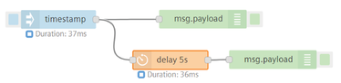
Execution duration of the flow
With this information, you get the duration of the complete execution time of the flow displayed under every node which starts or triggers the flow. Maximum execution time limit for a flow is 30 seconds, except the flow with power mode execution time limit is up to 120 seconds. In the below example, the execution time for the first flow output will be generated and thereafter the second flow output will be generated as per the specified delayed time in the delay node.
Usage of basic nodes
The Visual Flow Creator component has the following basic nodes:
- Input nodes
- Output nodes
Input nodes
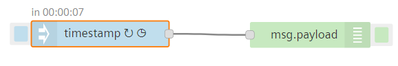
Input nodes trigger data to the flow. Each input node has one output. Use input nodes to supply data from other services. They generate messages for downstream nodes.
| Input nodes | Description |
|---|---|
 | - Shows an input node. - The blue button on the left triggers the input node. |
Output nodes
Output nodes send the data from the flow to other services or to the debug tab. Output nodes have one input. They consume the messages and trigger an action (for example sending an http response).
| Output Nodes | Description |
|---|---|
 | - Shows an output node. - The green button on the right deactivates or activates the output node. |
Usage of flow switch node
The Flow Switch node allows you to activate or deactivate a Visual Flow Creator flow tab.
Example
To activate or deactivate a Visual Flow Creator flow tab, follow these steps:
-
Create the flow as shown below:

-
Edit http request node properties:
- Method: GET
- Use Industrial IoT service: Check the option
- Industrial IoT path: /api/vfc/v3/flows/projects/0/tabs/8888a447.745cc8?user=steve@email.com
Note
"8888a447.745cc8" is a flow tab unique ID for the selected tab. This unique ID of the selected tab is available in Visual Flow Creator URL.
3.Edit function node properties: - Code: msg.payload = !msg.payload.disabled; return msg;
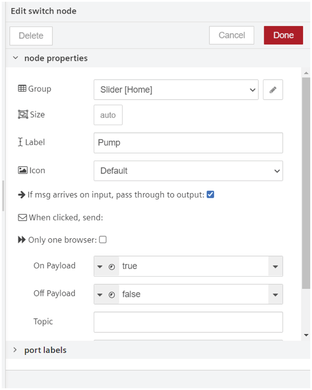
4.Edit switch node properties:
Note
"8888a447.745cc8" is a flow tab unique ID for the selected tab. This unique ID of the selected tab is available in Visual Flow Creator URL.
3.Edit function node properties: - Code: msg.payload = !msg.payload.disabled; return msg;
4.Edit switch node properties:
5.Edit flow switch node properties:
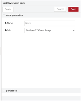
6.Save and execute the flow.
Result
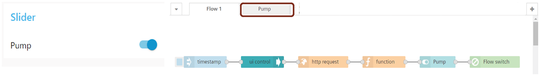
To view the output, activate and deactivate Visual Flow Creator flow tab by using toggle button in the dashboard. After activating or deactivating the toggle button in the dashboard, refresh Visual Flow Creator editor page to view the output.
Activated "Pump" tab
Deactivated "Pump" tab
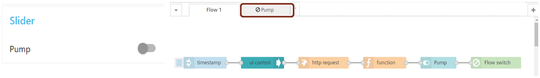
After "Pump" flow tab is deactivated, the flows are disabled to execute under this tab.
Usage of image output node
The simple image output node allows you to preview the results of face detection, object recognition and so on.
Click  button of the image output node can be used to enable or disable the image preview. It is recommended (for performance) to disable or remove any Image-Output nodes that are not being used.
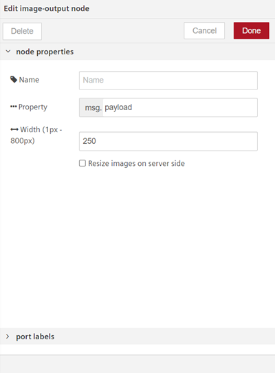
You can edit the Image output node properties with the following parameters:
| Parameters | Description |
|---|---|
| Property | This node expects the selected msg.property (default msg.payload) to contain one of the following formats: - A base64 encoded string - A buffer - A URL to an image Sending a blank or null payload will remove/hide the preview panel. |
| Width (1px - 800px) | The width (in pixels) of the image needs to be specified to display in the flow. |
| Resize images on server side | When too much data is sent to the browser, the flow editor can become unresponsive. - When it is activated, the images will be resized (to the specified width) on the server side and then those small thumbnail images will be send to the browser, to reduce the bandwidth. - When it is de-activated, the (original) large images will be send to the browser. Once the image is arrived to the browser, it will resize the image to the specified width. |
Example
To preview the image output using image output node, follow these steps:
-
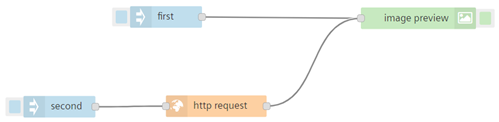
Create the flow as shown below:
-
Edit the first inject node properties to enter the URL as a string value:
- Payload(string) example URL:
https://upload.wikimedia.org/wikipedia/commons/thumb/5/5f/Siemens-logo.svg/250px-Siemens-logo.svg.png
- Payload(string) example URL:
-
Edit the second inject node properties an set the payload value as timestamp
-
Edit http request node properties:
- Enter the example URL:
https://upload.wikimedia.org/wikipedia/commons/thumb/5/5f/Siemens-logo.svg/250px-Siemens-logo.svg.png - Return: Select "a binary buffer" from the drop-down
- Enter the example URL:
-
Edit image output node properties:
- Property:
msg.payload - Width (1px - 800px): 250
- Resize images on server side - Uncheck for "first" flow and check for "second" flow to reduce the bandwidth
- Property:
-
Save and execute the flow.
Result
"first" flow
When you execute the "first" flow for multiple times, it will preview the same image as the result if the URL consists of multiple images.

"second" flow
When you execute the "second" flow for multiple times, it will preview the different image as the result if the URL consists of multiple images.
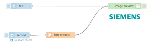
For both the flows "first" and "second", when you click on the image preview then it will be disappeared.
Usage of junction-nodes
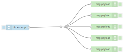
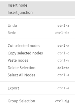
Junction node allows you to combine the multiple wires which are connected to multiple nodes. To insert the junction, "Right-click" on the work area and click "Insert junction".
Junction node is displayed as shown below:

Example
The following example displays the usage of the junction node: