Overview of Modbus TCP protocol for MindConnect IoT2050
The Modbus protocol is supported for the MindConnect IoT2050. You can select the protocol type Modbus TCP while adding a new data source in Asset Manager.
Modbus configuration
The Modbus configuration view is only visible after a successful onboarding of the MindConnect IoT2050. The MindConnect IoT2050 Version must be higher than V3.3.0.2.
The following picture shows the protocol selection in Asset Manager:
For more information about how to create a new data source see chapter Adding a data source for MindConnect IoT2050.
Modbus TCP data source parameter
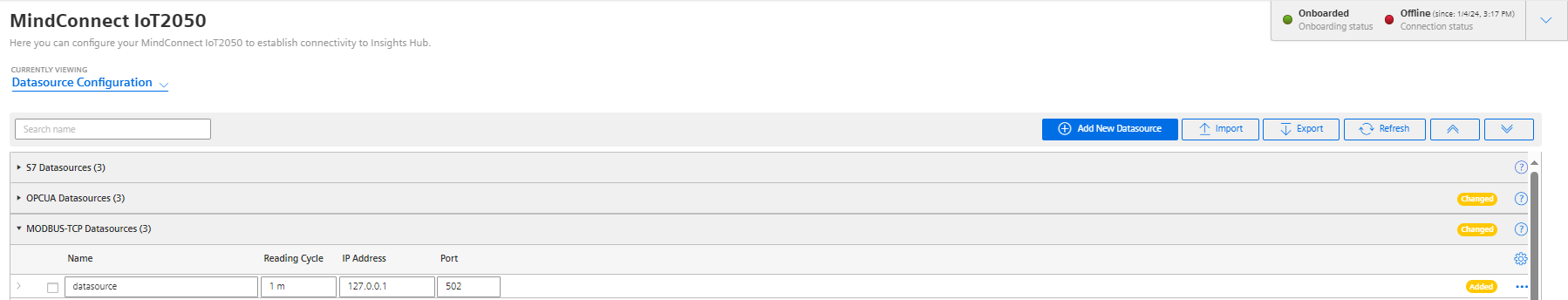
To connect a Modbus TCP device, you need to select the Modbus TCP protocol and enter the following data source parameters:
| Parameter | Description |
|---|---|
| IP Address | IP address of the Modbus device |
| Port | Port number of the Modbus device (default: 502) |
The following parameters are optional and can be adjusted for collecting data from slow Modbus devices:
| Parameter | Description |
|---|---|
| byteTimeout | You can set the timeout interval between two consecutive bytes of the same message received from the Modbus device. If the delay between is longer than the given timeout, an error will be generated. Range: 500ms (default) … 2000ms |
| responseTimeout | You can set the timeout interval used to wait for a response from the Modbus device. If the waiting before receiving the response is longer than the given timeout, an error will be generated. Range: 500ms (default) … 60000ms |
| responseSuspensionTime | If a byte timeout or a response timeout was detected, then this waiting time is added before the next request is started. During this time any response from the Modbus device will be flushed. Range: 0ms … 45000ms. (default: 1000ms) |
| requestDelay | You can set the time between the response from the Modbus device and the next request to this Modbus device. Range: 0ms (default) … 10000ms |
Modbus TCP data point parameter
To collect the data of your Modbus TCP device, you must add new data points.
The following graphic shows the data point parameter window:
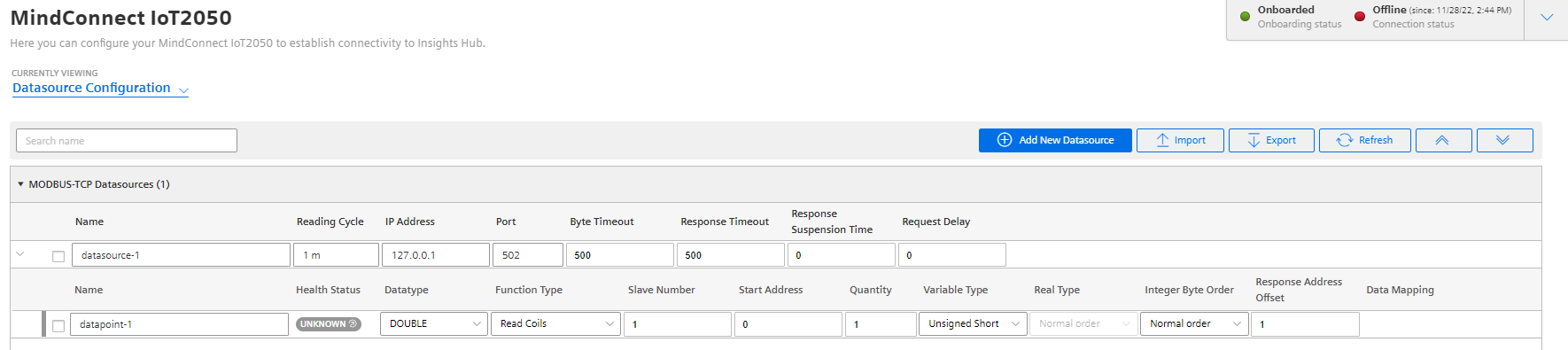
The following table shows the parameter of the Modbus TCP data point window:
| Parameter | Description |
|---|---|
| Data Type | Data type supported by backend (e.g. INT). |
| Slave Number | Address/Slave number of the Modbus device. |
| Start Address | Start address (offset) of the data. |
| Quantity | Quantity of data to be read. |
| VariableType | You can choose the following variable types of the Modbus data to be read: 1: char : 8 bits, 2: unsigned char : 8 bits, 3: short : 16 bits, 4: unsigned short : 16 bits, 5: long : 32 bits, 6: unsigned long : 32 bits, 7: float : 32 bits, 8: double : 64 bits, 9: ascii-text : 8 bits / char |
| Real Type | Real type - determines, if the registers of real values have to be processed in reversed order. 0: Normal order, 1: Reversed order, 2: Byte swap order, 3: Word swap order, Real types 2 and 3 are available from V03.04.02.01. |
| Integer Byte Order | It determines in which byte order format the read value will be processed (default: 0) 0: Normal order (big-endian) 1: Reversed order (little-endian byte swap) 2: Byte swap order (big-endian byte swap) 3: Word swap order (little-endian) Note: Integer byte order is available for 16 bits and 32 bits variable types only, and it is supported for the version starting from MindConnect IoT2040 V03.04.02.13. |
| Response Address Offset | Offset of the data to return in register units. |
| Response Quantity | Quantity of the returned data. Only for string data a value greater than 1 is supported. |
TCP Gateway slave number
If you are using a TCP Gateway, you must select the appropriate slave number for the configuration of the data points.
The following table shows the parameter of the Modbus TCP datapoint window for Function Type and Acquisition Type:
| Function Type | Acquisition Type |
|---|---|
| The function type depends on the type of the data (see manual of the Modbus device). | The acquisition type depends on the selected function type. |
| 1: Read Coils | Read |
| 2: Read Inputs | Read |
| 3: Read Holding Registers | Read |
| 4: Read Input Registers | Read |
| 5: Write Single Coil1) | Write |
| 6: Write Single Register1),2) | Write |
| 15: Write Multiple Coils1) | Write |
| 16. Write Multiple Registers1),3) | Write |
| 22: Mask Write Register1) | Write |
| 23: Read/Write Multiple Registers1) | Write |
- Currently function codes 1..4 are supported.
- 1) Supported since MindConnect IoT2050 V03.07.01.00 b003.
- 2) Used to write values to data points with variable types using a single register (example: short).
- 3) Used to write values to data points with variable types using one or more registers (example: long or double).
Addressing:
The information is stored in the Modbus Slave device in 4 different tables. 2 tables store on/off discrete values (coils) and two store numerical values (registers). Each coil is 1 bit long and assigned a data address between 0 and 65535. Each register has the size of 1 word(16 bits/ 2 bytes) and has a data address between 0 and 65535.
| Coil/ Register numbers | Data addresses | Function type | Table name |
|---|---|---|---|
| 1-9999 | 0 to 65535 | 1 | Read Coils |
| 10001-19999 | 0 to 65535 | 2 | Read Inputs |
| 30001-39999 | 0 to 65535 | 4 | Read Input Registers |
| 40001-49999 | 0 to 65535 | 3 | Read Holding Registers |
Coil / register numbers can be considered as location names since they do not appear in the configuration. The Data Addresses (Start Address) are used in the configuration.
Data Types:
| Data type | Length | Data range |
|---|---|---|
| BOOLEAN | 1 bit | True to False |
| INT | 4 bytes | −2147483648 to 2147483647 |
| LONG | 8 bytes | −9223372036854775808 to 9223372036854775807 |
| DOUBLE | 8 bytes | -9.9999999999999999999999999999999999999E+125 to 9.9999999999999999999999999999999999999E+125 |
| STRING | 1 - 255 bytes |
Modbus data types:
| Data type | Length | Data type number | Data range |
|---|---|---|---|
| char | 8 bits | 1 | -128 to 127 |
| unsigned char | 8 bits | 2 | 0 to 255 |
| short | 16 bits | 3 | -32768 to 32767 |
| unsigned short | 16 bits | 4 | 0 to 65535 |
| long | 32 bits | 5 | −2147483648 to 2147483647 |
| unsigned long | 32 bits | 6 | 0 to 4294967295 |
| float | 32 bits | 7 | -3.402823e+38 to -1.175 495e-38 +1.175 495e-38 to +3.402823e+38 |
| double | 64 bits | 8 | -1.7976931348623158e+308 to -2.2250738585072014e-308 +2.2250738585072014e-308 to +1.7976931348623158e+308 |
| ascii-text | 8 bits / char | 9 |
Examples:
| Example | Data type | Function type | Start address | Variable type | Response Address Offset | Response Quantity |
|---|---|---|---|---|---|---|
| Reading the first Holding Register, number 40001, has the start address 0. | int | Read Holding Registers | 0 | unsigned short or short | 0 | 1 |
| VariableType: 4 or 3 (unsigned short or short)Reading the second Input Register, number 30002, has the start address 1. | int | Read Input Registers | 1 | unsigned short or short | 0 | 1 |
| Reading a float (32 bits) from Input Register 30108 / 30109, has the start address 107. | double | Read Input Registers | 107 | float (reads two registers) | 0 | 1 |
| Reading a string. This example describes to read four letters from register 40006 and 40007. Each register contains two characters. | string | Read Holding Registers | 5 | unsigned short | 0 | 2 (registers) |
| Reading a Boolean from the Holding Register 40011, has the start address 10. If the hole Holding Register has the value 0 then it is displayed as 0. If one bit(or more) has the value 1 then it will be displayed as 1. | Boolean | Read Holding Registers | 10 | unsigned short or short | 0 | 1 |
Using Modbus register addresses directly
Usually, it is necessary to enter Modbus registered address decremented by 1 as "start address", but it may lead to confusion when comparing the data point's "start address" with the registered address from Modbus device's manual. Therefore, enter a negative value in the "response address offset" field to directly use the registered address from the Modbus device's manual as "start address". In case a negative value has been entered as "response address offset", this value will internally be subtracted from the given "start address" number to read the data from Modbus device. Positive "response address offset" values will be handled to address specific data within the read data if several registers need to be read to acquire the data from Modbus device as data block and the necessary data itself is only a part of that data block.
Supported since:
- MindConnect IoT2050 V03.04.03.03 b001
Samples:
| Using decremented start address | Using address from manual | Getting data from a read data block | |
|---|---|---|---|
| Registered address from Modbus device manual | 303 | 303 | 64001 |
| Start address | 302 | 303 | 640011) |
| Quantity | 1 | 1 | 27 |
| Response address offset | 0 | -1 | 11 |
| Response quantity | 1 | 1 | 16 |
1) Sample start offset as documented in SENTRON PAC manual - can be used without decrementing it by 1.