Reason Tree
A reason tree is a structured way to show the various states that a machine or line can be in. OEE is a continuous improvement tool and one crucial step towards improvement is the analysis of downtime reasons of machines and lines. The companies using OEE can try to solve and monitor the performance of their actions once the main levers in the downtime reasons, for example, supply always coming too late at the stations, are discovered. A detailed reason tree is required to enable this type of examination.
Reason trees are built for same machine types or lines of machines. As a result, Insights Hub OEE allows you to add multiple reason trees for different machines or lines. Only in rare cases one reason tree can cover all machine or line states in a factory. The user can decide how to structure reason trees. Typically, a reason tree contains more reasons than the number of states for each machine, which it can log through different status codes. The reason for this is, that the user can later modify the existing collected reasons and change them if the collected state does not reflect the real machine behavior. For instance, the machine reports an emergency stop of the machine but in reality, it was not caused by the machine itself, but the operator had pushed the emergency button. Then in the post-production analysis, someone can assign the right reason to the registered event and improve the analysis. This only works if the causes are also developed that are not reported by the machine through status codes.
Typically, a reason tree is built out of the following categories:
- Time Category (described in the Section Time Model)
- State (describes the machine state)
- Reason Layer 1
- Reason Layer 2
- Reason Layer 3
- Reason Layer 4
The reason tree time categories are fixed and cannot be further modified by a user. The second item state describes what type of state the machine, on a higher level. This could be, for example, run, idle, stop, emergency, end of shift, etc. The further details which describe the machine state are then built through the tree structure and the different reason layers.
The following image shows an example of the reason tree:
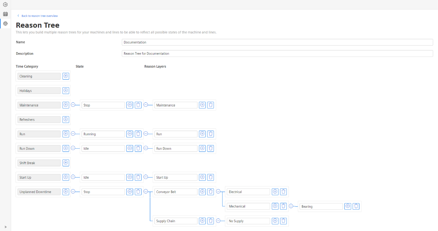
In the example above, multiple reasons are shown. Here, we focus on a couple of reasons out of the unplanned downtime time category. As explained before, the reason tree consists of time category, state, and then the multiple reason layers. In the above example, there are a couple of reasons shown that share the same state – in this case, it is “stop”, so the machine is in a stop mode and not operating. After the stop state, the reason tree author defined multiple reason layers to describe different reasons for stop states. One of the stop states is related to the supply chain reason, whereas another stop state is related to the conveyor belt reason.
As shown in the example, the following reason layers describe further the stop state. In case of the supply chain reason, the next level of detail is “no supply”, so that the machine is not having further supply; therefore, unable to operate. In the conveyor belt reason, the next layer splits up into multiple reasons. The problem could be either a mechanical or an electrical issue. In the example, there is also another reason layer attached to the mechanical reason. In the third reason layer, a bearing reason is described. The two examples described above should show how the user can build complex and detailed reason trees that can reflect all the different kinds of machine states. For in-depth analysis on downtime reasons later, it is useful to reflect as many states as possible in the reason tree.
For more information to set up the Reason Tree, refer Section Configuring Reason Tree.